Contactless power transmitting system having overheat protection function and method thereof

a transmission system and contactless technology, applied in the direction of battery overheat protection, safety/protection circuit, transportation and packaging, etc., can solve the problems of reducing the lifespan affecting the service life of the battery pack, so as to prevent the generation of errors and prevent the overheating of the battery cell module

Active Publication Date: 2013-05-02
GE HYBRID TECH
View PDF10 Cites 11 Cited by
  • Summary
  • Abstract
  • Description
  • Claims
  • Application Information

AI Technical Summary

Benefits of technology

[0016]According to an aspect of the invention, the contactless power transmitting apparatus may transmit a second power, of lower wattage than the first power, to the contactless power receiving apparatus, if the overheat alarm signal is received, to charge the battery cell module with the second power, thereby preventing the battery cell module from overheating.
[0017]According to an aspect of the invention, after the contactless power receiving apparatus generates the overheat alarm signal, the charging unit may switch to a second power charging mode in which the battery cell module is charged with the second power, thereby preventing generation of an error.

Problems solved by technology

This instantaneous discharge phenomenon causes abrasion of the terminals, and creates a risk of an accident such as a fire or the like if foreign materials have accumulated in either terminal.
In addition, the electrical energy charged in the battery pack naturally discharges into the environment through the terminal of the battery pack due to moisture or the like, such that a lifespan of the battery pack may decrease and performance thereof may deteriorate.

Method used


Image

  • Contactless power transmitting system having overheat protection function and method thereof
  • Contactless power transmitting system having overheat protection function and method thereof
  • Contactless power transmitting system having overheat protection function and method thereof

Examples


Embodiment Construction

[0039]Reference will now be made in detail to the present embodiments of the present invention, examples of which are illustrated in the accompanying drawings, wherein like reference numerals refer to the like elements throughout. The embodiments are described below in order to explain the present invention by referring to the figures, and to present a principle and a concept of the present invention in a manner that most usefully and easily described the present invention.

[0040]The following detailed description is only an example and only illustrates exemplary embodiments of the present invention. For basic understanding of the present invention, unnecessary details and additional embodiments of the present invention that may be executed by those skilled in the art will not be described.

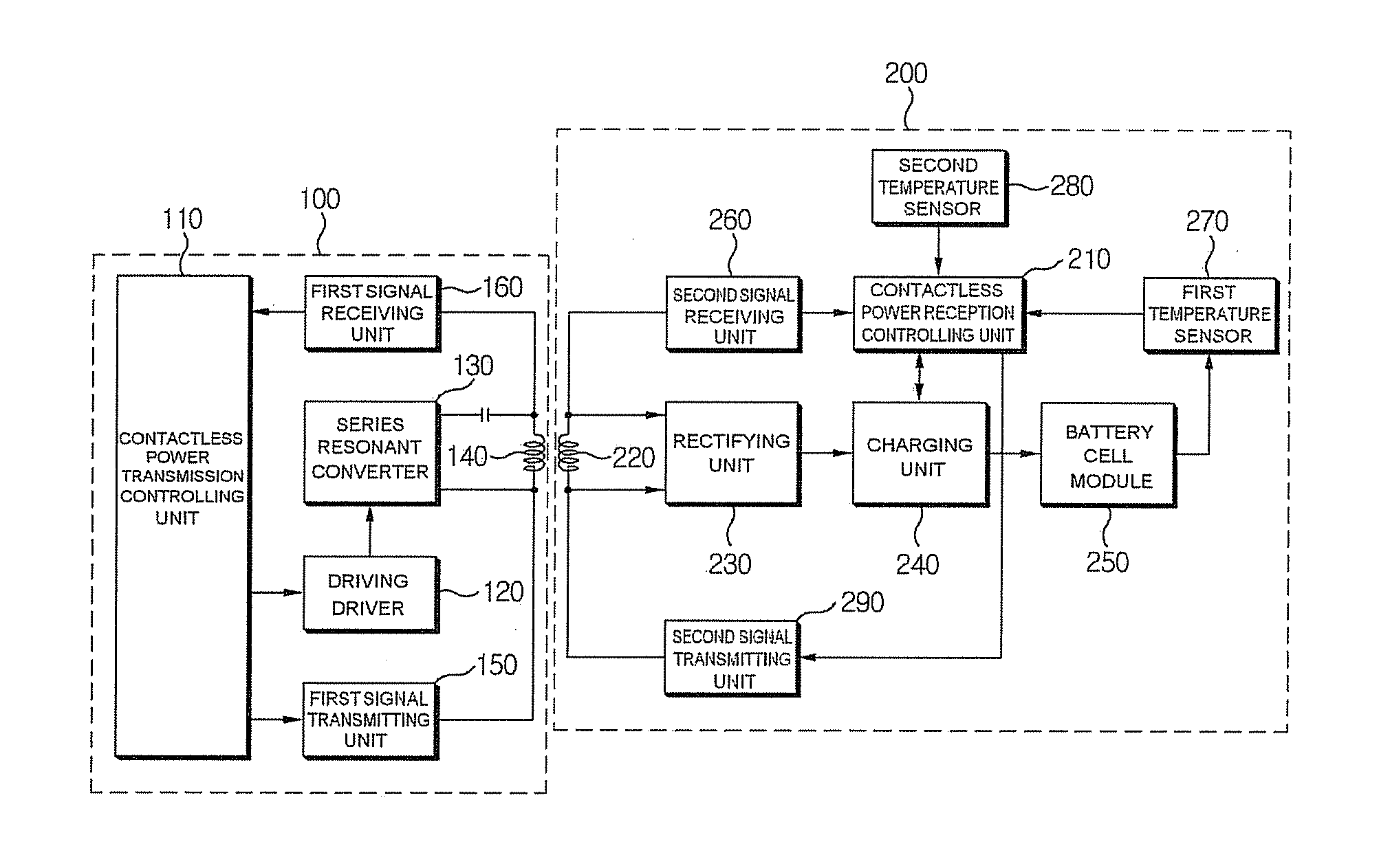
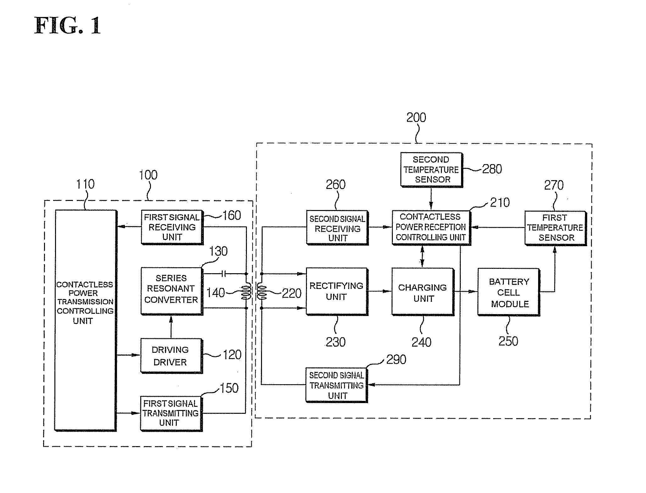
[0041]According to an aspect of the invention depicted in FIG. 1, a contactless power transmitting system may comprise a contactless power transmitting apparatus 100 and a contactless power receivi...


PUM

PropertyMeasurementUnit
temperatureaaaaaaaaaa
poweraaaaaaaaaa
temperatureaaaaaaaaaa

Abstract

Disclosed herein are a contactless power transmitting system having an overheat protection function, which protects a battery cell module from damage due to overheating while the battery cell module is being charged, and a method thereof. In the contactless power transmitting system, a contactless power transmitting apparatus transmits a first power to a contactless power receiving apparatus through a power transmitting coil to charge the battery cell module with the first power, and transmits a second power, of lower wattage than the first power, to the contactless power receiving apparatus through the power transmitting coil to charge the battery cell module with the second power if an overheat alarm signal is received from the contactless power receiving apparatus, thereby making it possible to fully charge the battery cell module while preventing overheating of the battery cell module.

Description

CROSS-REFERENCE TO RELATED APPLICATIONS[0001]This application claims the benefit of Korean Application No. 10-2011-0113239, filed Nov. 2, 2011 in the Korean Intellectual Property Office and entitled “Contactless Power Transmitting System Having Overheat Protection Function And Method Thereof”, the disclosure of which is incorporated herein by reference in its entirety.BACKGROUND OF THE INVENTION[0002]1. Field of the Invention[0003]The present invention relates to a contactless power transmitting system having an overheat protection function, which protects a battery cell module from damage due to overheating while the battery cell module is being charged, and a method thereof.[0004]2. Description of the Related Art[0005]Generally, a portable terminal such as a cellular phone, a personal digital assistant (PDA), or the like, includes a battery pack. The battery pack may be charged with a power supplied from an external charging apparatus, and may supply the charged power to the porta...

Claims


Application Information

Patent Timeline
Patent Type & Authority Applications(United States)
IPC IPC(8): H02J7/04H01F38/14H02J7/00
CPCH02J5/005H02J7/025H02J2007/0001H02J7/0091H02J7/0029H02J7/007192H02J7/00045H02J7/00309H02J50/80H02J7/007194H02J50/12H02J50/10H02J7/00041
Inventor JUNG, CHUN-KIL
Owner GE HYBRID TECH
Why Eureka
Try Eureka