Profile measuring apparatus, structure manufacturing system, method for measuring profile, method for manufacturing structure, and non-transitory computer readable medium

a technology for manufacturing systems and measuring devices, applied in the direction of manufacturing tools, television systems, instruments, etc., can solve the problem of increasing the probability of reducing the measurement accuracy

Active Publication Date: 2013-05-02
NIKON CORP
View PDF8 Cites 25 Cited by
  • Summary
  • Abstract
  • Description
  • Claims
  • Application Information

AI Technical Summary

Problems solved by technology

In the profile measuring technique, in a case that brightness of the image taken by the imagi

Method used


Image

  • Profile measuring apparatus, structure manufacturing system, method for measuring profile, method for manufacturing structure, and non-transitory computer readable medium
  • Profile measuring apparatus, structure manufacturing system, method for measuring profile, method for manufacturing structure, and non-transitory computer readable medium
  • Profile measuring apparatus, structure manufacturing system, method for measuring profile, method for manufacturing structure, and non-transitory computer readable medium

Examples


first embodiment

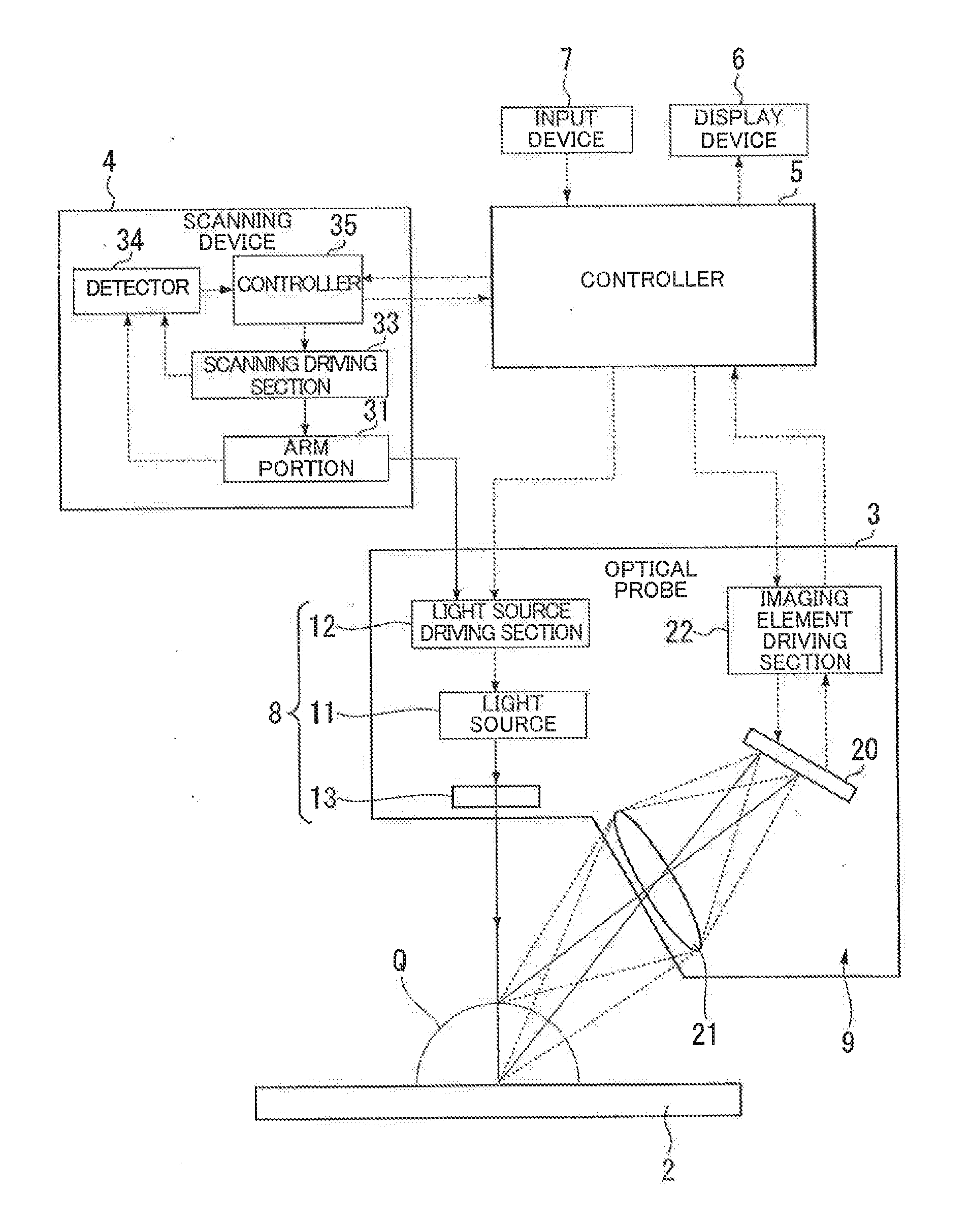
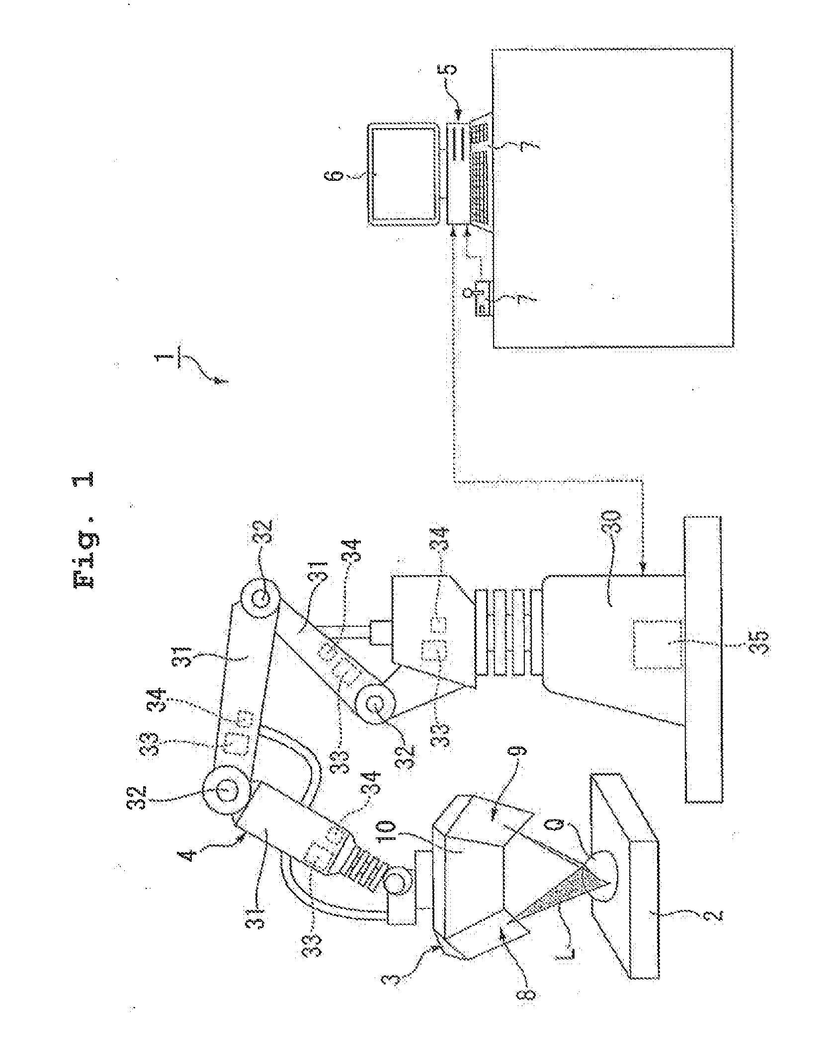
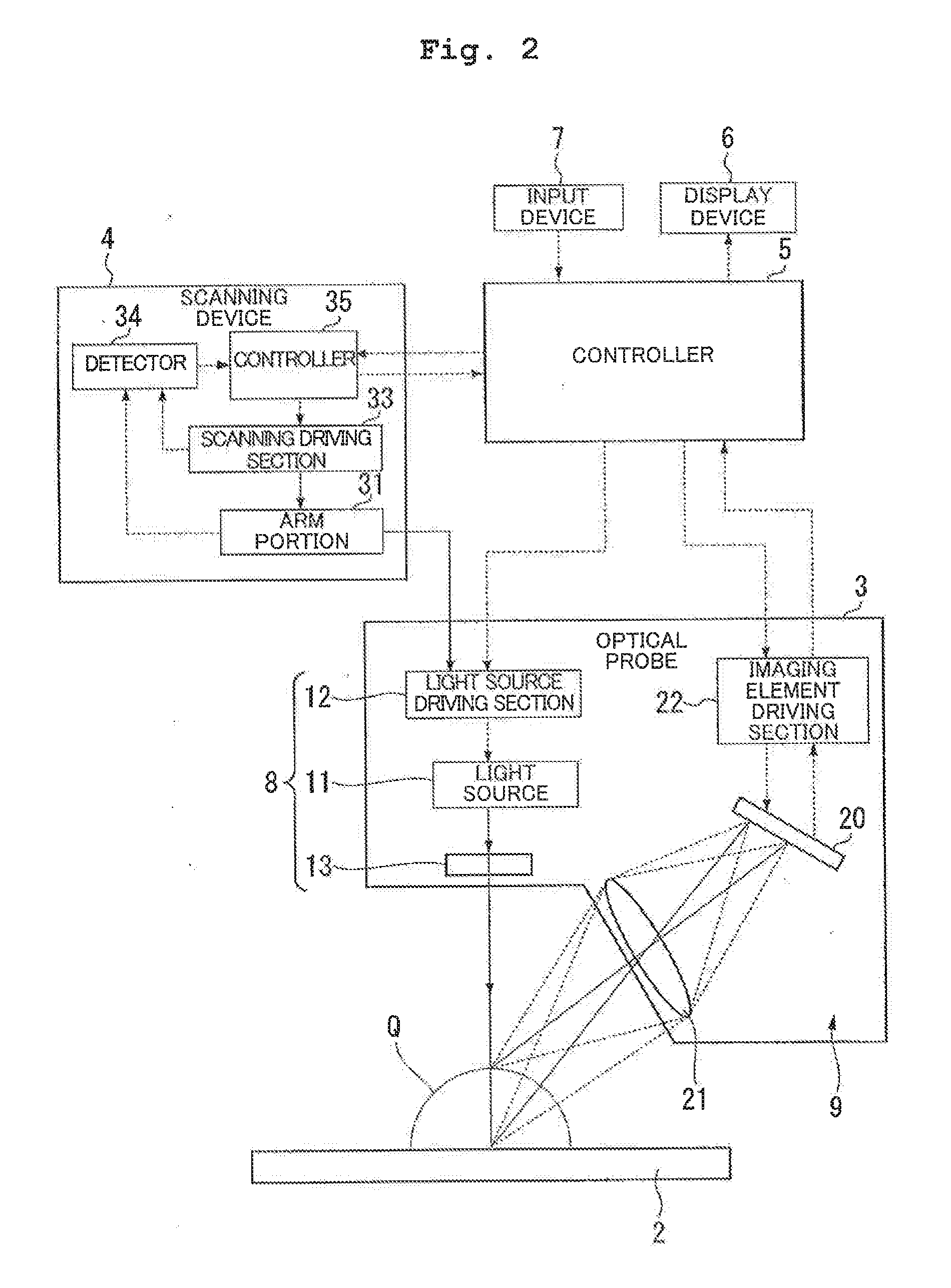
[0045]An explanation will be made about a schematic construction of a profile measuring apparatus according to the first embodiment. FIG. 1 schematically shows the profile measuring apparatus of the first embodiment. FIG. 2 shows a construction of the profile measuring apparatus of the first embodiment.

[0046]A profile measuring apparatus (profile measuring system) 1 as shown in FIG. 1 is provided with a stage device 2, an optical probe 3, a scanning device 4, a controller 5, a display device 6, and an input device 7. The profile measuring apparatus 1 of this embodiment is capable of measuring a profile of an object Q, like a Coordinate Measuring Machine (CMM), an image measurement microscope, etc.. The profile measuring apparatus 1 of this embodiment is capable of measuring a three-dimensional profile of the object Q arranged on the stage device 2 by an optical cutting method. The profile measuring apparatus 1 of this embodiment repeatedly performs unit measurements, in which a part...

second embodiment

[0183]Next, an explanation will be made about the second embodiment. The components, which are the same as or equivalent to those of the embodiment described above, are designated by the same reference numerals, any explanation of which will be simplified or omitted as appropriate in the second embodiment.

[0184]FIG. 18 is a diagram showing a method for adjusting an exposure amount according to the second embodiment. FIG. 19 is a flowchart schematically showing a method for measuring a profile according to the second embodiment. In this embodiment, each of the processes in the method for measuring the profile as shown in FIG. 19 is carried out by each of the sections of the profile measuring apparatus 1 described in the first embodiment. The unit measurement process is executed a plurality of times by the profile measuring apparatus 1 of this embodiment to obtain the profile information of the object Q.

[0185]As shown in FIG. 18, in this embodiment, the unit measurement period include...

third embodiment

[0195]Next, an explanation will be made about the third embodiment. The components, which are the same as or equivalent to those of the embodiments described above, are designated by the same reference numerals, any explanation of which will be simplified or omitted as appropriate in the third embodiment.

[0196]FIG. 20 is a schematic configuration diagram of an imaging device of a profile measuring apparatus according to the third embodiment. FIG. 21 is a circuit diagram showing a pixel of the imaging device of the profile measuring apparatus according to the third embodiment.

[0197]The profile measuring apparatus of this embodiment includes an imaging device 100 shown in FIG. 20. The imaging device 100 of this embodiment includes an imaging element 101 and an imaging element driving section 102. The imaging element 101 of this embodiment includes a CMOS image sensor which reads out the electric charge generated in the photodiode by a CMOS. A construction and operation of the CMOS ima...


PUM


Abstract

A profile measuring apparatus includes: a light source device from which a projection light is irradiated, the projection light having a light amount changing with lapse of time in a first period and a predetermined spatial distribution; an imaging element; a second period setting section which sets a second period including at least a part of the first period; and a profile information obtaining section which obtains an information of the profile of the object based on an image data taken by the imaging element in the second period. The second period setting section sets the second period based on a light amount of a light which comes into the imaging element at the time of an imaging performed before one imaging performed in the second period; and a light amount change pattern of the projection light changing with lapse of time in the first period.

Description

CROSS-REFERENCE TO RELATED APPLICATIONS[0001]The present application claims priority from Japanese Patent Application No. 2011-240470, filed on Nov. 1, 2011, the disclosure of which is incorporated herein by reference in its entirety.BACKGROUND[0002]1. Field of the Invention[0003]The present invention relates to a profile measuring apparatus, a structure manufacturing system, a method for measuring a profile, a method for manufacturing a structure, and a non-transitory computer readable medium.[0004]2. Description of the Related Art[0005]A profile measuring technique using an optical cutting method etc. is used, for example, for measuring a profile of an object such as an industrial product. The profile measuring technique relates, for example, to a technique in which an image of a surface of the object to which light is irradiated is taken by an imaging element and the profile of the object is measured based on the result (see, for example, Japanese Patent No. 3,819,275).[0006]In t...

Claims


Application Information

Patent Timeline
IPC IPC(8): H04N7/18
CPCG01B21/045G01B11/25B25J11/00
Inventor YAMADA, TOMOAKI
Owner NIKON CORP
Why Eureka
Try Eureka