Rotating device to change lighting angle

Inactive Publication Date: 2013-05-02
ALDER OPTOMECHANICAL
View PDF9 Cites 13 Cited by
  • Summary
  • Abstract
  • Description
  • Claims
  • Application Information

AI Technical Summary

Benefits of technology

The present invention provides a lamp rotating device that can change the lighting angle. It consists of a light tube, a lighting module, two fixed ends, and two rotating parts. The lighting module is installed inside the light tube and each fixed end is fixed on the open end of the light tube. Each rotating part is installed between a fixed end and the open end of the light tube. One side of the rotating part interferes with the light tube so that when the rotating part moves, the light tube rotates along with it, resulting in a simple and sturdy device for changing the lighting angle.

Problems solved by technology

However, general consumers still use traditional lamps, therefore in a short period of time, if traditional lamps are not fully out of order, most of consumers will not changes to new LED lamps soon.
However, under current lamp specifications, to use light emitting diode (LED) as the light source, although the existing power supply plug is still available, but it cannot change or adjust lighting angle which cannot meet users' demand and causes inconvenience.

Method used


Image

  • Rotating device to change lighting angle
  • Rotating device to change lighting angle
  • Rotating device to change lighting angle

Examples


second embodiment

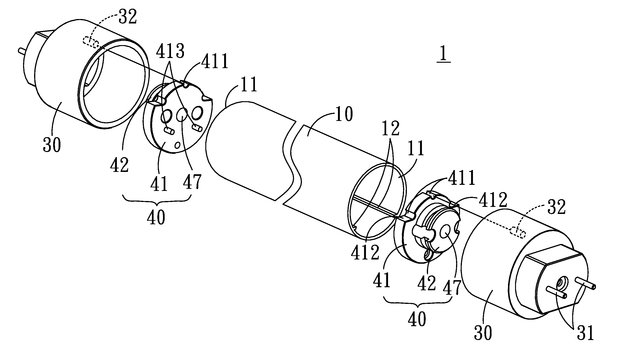
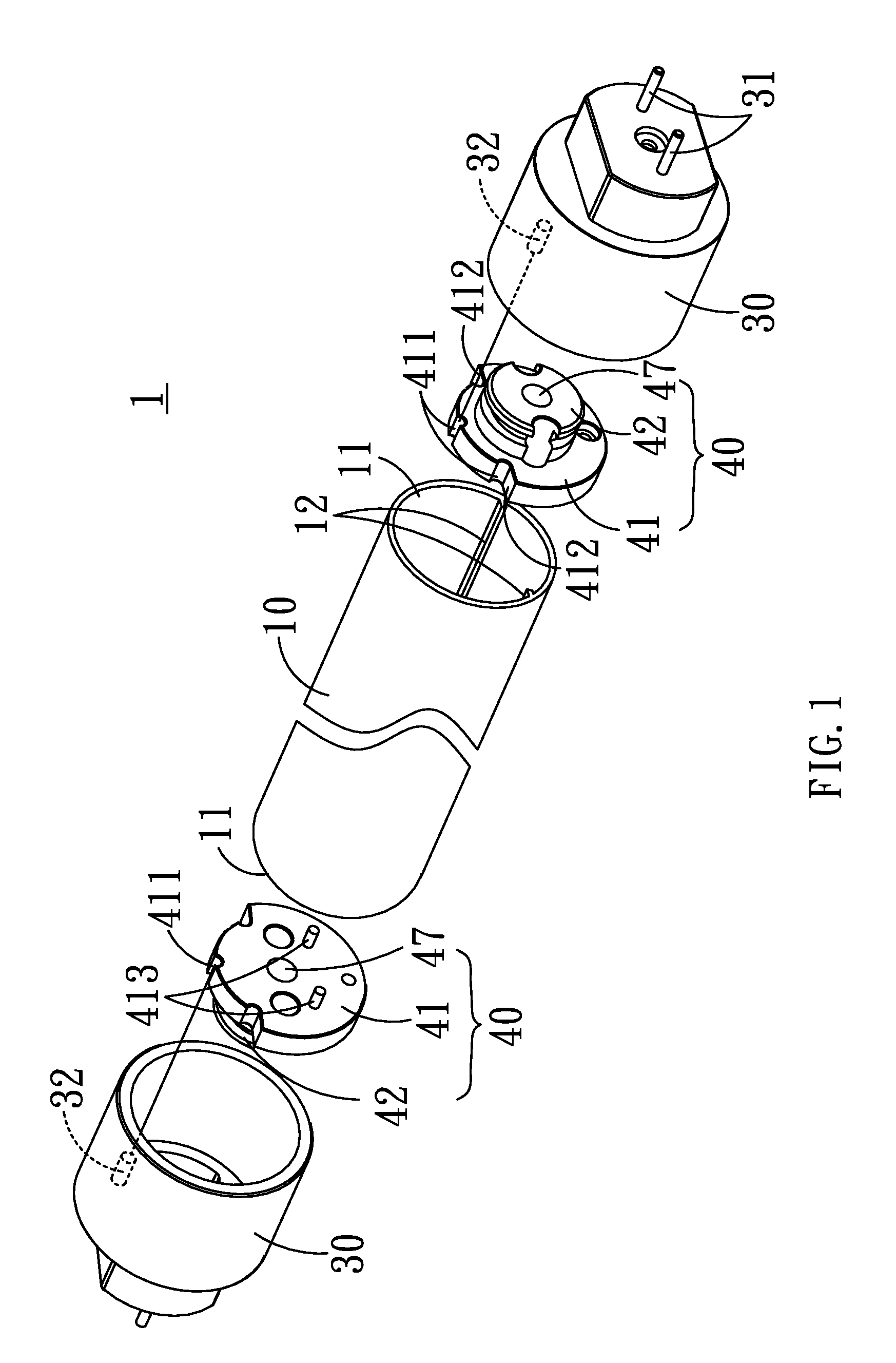
[0030]The second embodiment is fixed on a regular lamp holder by two fixed ends 30 (not shown in Fig.); users rotate the light tube 10 to adjust lighting angle, the light tube 10 rotates on the brakes 34 of the ring slots 431 on both ends, the main bodies 43 on both ends rotate simultaneously, the guidances 44 on two ends rotate from the original guidance slot 33 to other corresponding guidance slot 33, as shown in FIG. 7; the light tube 10 is on the corresponding angle. Users can base on real need, by rotating light tube 10 to turn corresponding rotating parts 40 to adjust the light tube 10 for the best lighting angle.

[0031]Furthermore, each fixed end 30 has two stoppers 35, when the light tube 10 rotates, the guidances 44 on two ends rotate simultaneously, when the guidances 44 touch one of the stopper 35, the stopper 35 keeps the light tube 10 from turning to prevent users from over rotate the light tube 10 as a result of excessive rotation to damage the device.

[0032]With referen...

third embodiment

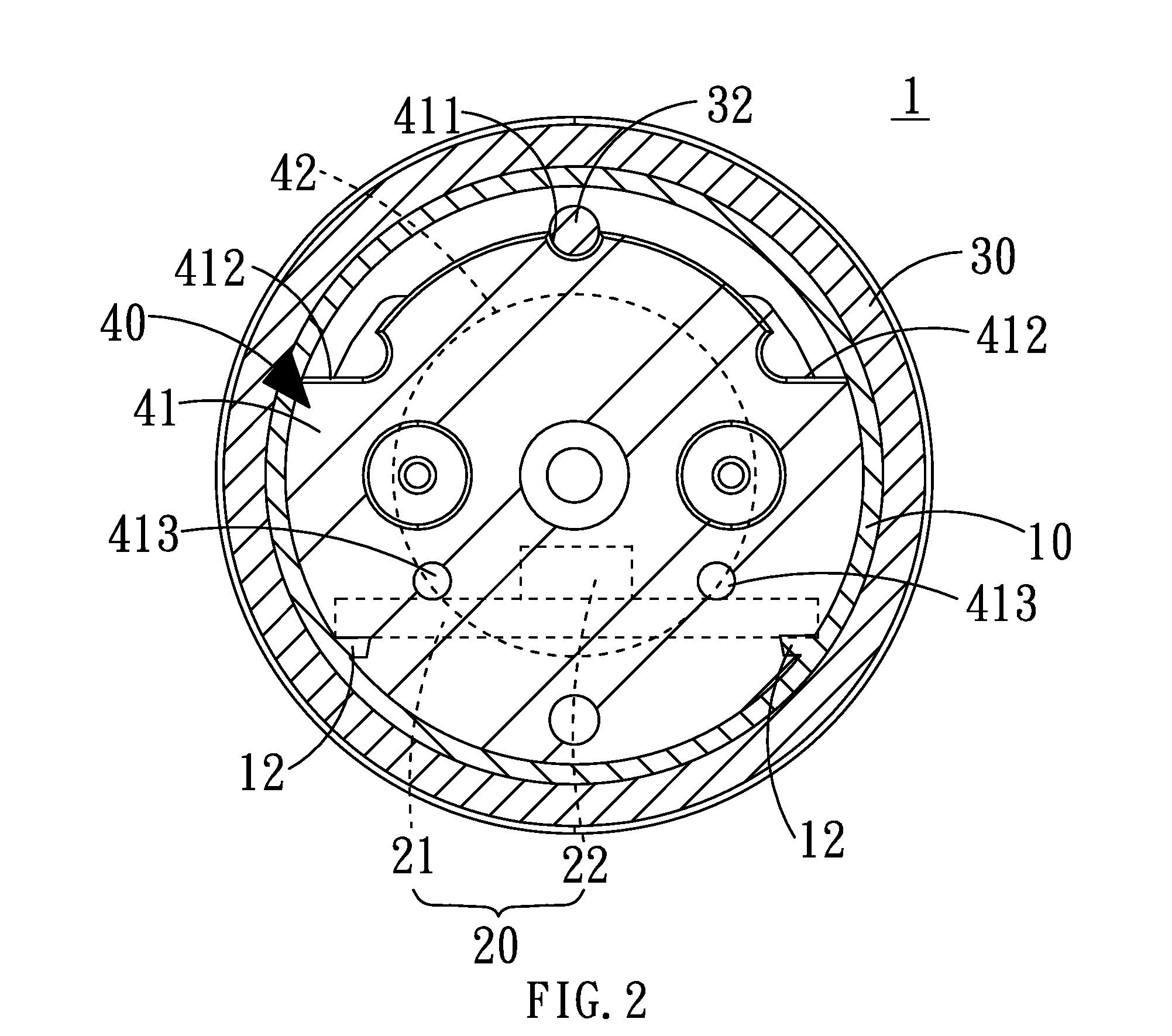
[0033]The third embodiment is fixed on a regular lamp holder by two fixed ends 30 (not shown in Fig.); users rotate the light tube 10 to adjust lighting angle, the light tube 10 rotates along the pivots 42 on both ends, the main bodies 43 on both ends rotate simultaneously, the convexes 451 turn from the original concave 433 original locations to other corresponding concave 433 locations; when convexes 451 on the new corresponding concave 433 locations, as shown in FIG. 11, the light tube 10 is on the corresponding angle. Users can base on real need, by rotating light tube 10 to turn corresponding rotating parts 40 to adjust the light tube 10 for the best lighting angle. A plurality number of concaves 433 can be on the plates 45 and corresponding convexes 451 are on the main bodies 43 for the same effect.

[0034]Furthermore, a curve slot 434 is on the main body 43 facing the plate 45 to have the fasteners 46 lock the plate 45 from outside of the fixed end 30; the end of the fastener 4...


PUM


Abstract

A lamp rotating device to change a lighting angle includes a light tube, a lighting module, two fixed ends and two rotating parts, an open is on both ends of the light tube, two fixed ends each is installed on one open, each of the rotating part is installed between the fixed end and the open respectively, one side of the rotating part interferes with light tube to have the light tube rotate along the fixed end by the movements of rotating part, and change a lighting angle.

Description

BACKGROUND OF THE INVENTION[0001]1. Field of the Invention[0002]The present invention relates to a lamp rotating device thereof, in particular to a lamp rotating device to change lighting angle thereof.[0003]2. Description of the Related Art[0004]Heretofore, it is known that Light Emitting Diode LED is a solid state semiconductor component, by means of current passes through diode to convert electrical energy into lighting. LED has advantages as small volume, light weight, rapid reaction speed and no pollution, that makes LED application gradually expands to all industry. Initially LED faced insufficient brightness and low lighting efficiency bottlenecks, but high power LED developed afterwards solved insufficient brightness problem, LED gradually steps into high efficiency lighting source market, and gradually replaces traditional tungsten lamps, is a potential product in the future to replace traditional lighting products.[0005]However, general consumers still use traditional lamp...

Claims


Application Information

Patent Timeline
IPC IPC(8): F21V21/14
CPCF21V21/14F21Y2103/003F21V21/30F21V19/008F21Y2103/10F21Y2115/10F21K9/65F21K9/275F21K9/272
Inventor LEE, CHIEN-KUOLU, CHING-TAIHUANG, PO-CHENGSU, YI-CHENG
Owner ALDER OPTOMECHANICAL
Why Eureka
Try Eureka