Electrical power connector

a technology of electrical power connectors and conductors, applied in the direction of electrical equipment, connection, coupling device connections, etc., can solve the problems of affecting system performance and operating safety, increasing temperature, etc., and achieves the effect of facilitating heat dissipation, reducing the temperature of the conducting terminal, and minimizing the variation of the electrical characteristics of the electrical power connector

Inactive Publication Date: 2013-05-02
ACES ELECTRONICS CO LTD
View PDF4 Cites 25 Cited by
  • Summary
  • Abstract
  • Description
  • Claims
  • Application Information

AI Technical Summary

Benefits of technology

[0008]The present invention has been accomplished under the circumstances in view. It is therefore the main object of the present invention to provide an electrical power connector, which effectively reduces the operating conducting terminal impedance and temperature.
[0010]Subject to the thermal conductivity characteristics of the metal plates, the arrangement of the heat dissipation mechanism facilitates heat dissipation to effectively lower the temperature of the conducting terminals, thereby minimizing variation of the electrical characteristics of the electrical power connector.
[0011]Further, the metal plates of high thermal conductivity of the heat dissipation mechanism can be U-shaped meal plates respectively capped on the top and bottom sides of the mating portions of the electrically insulative housing. Alternatively, the metal plates of high thermal conductivity of the heat dissipation mechanism can be angle plates respectively capped on the four corner areas of the mating portions of the electrically insulative housing. Further, the heat dissipation mechanism can also be covered on the mating portions as well as other part of the electrically insulative housing to enhance heat dissipation, increasing the current carrying capacity of the electrical power connector.

Problems solved by technology

With respect to power supply, conducting a high-current power supply through a power circuit will increase the impedance, causing a rise in temperature.
When conducting a high current to cause a rise in impedance, heat will be produced, affecting system performance and operating safety.

Method used


Image

  • Electrical power connector
  • Electrical power connector
  • Electrical power connector

Examples


Embodiment Construction

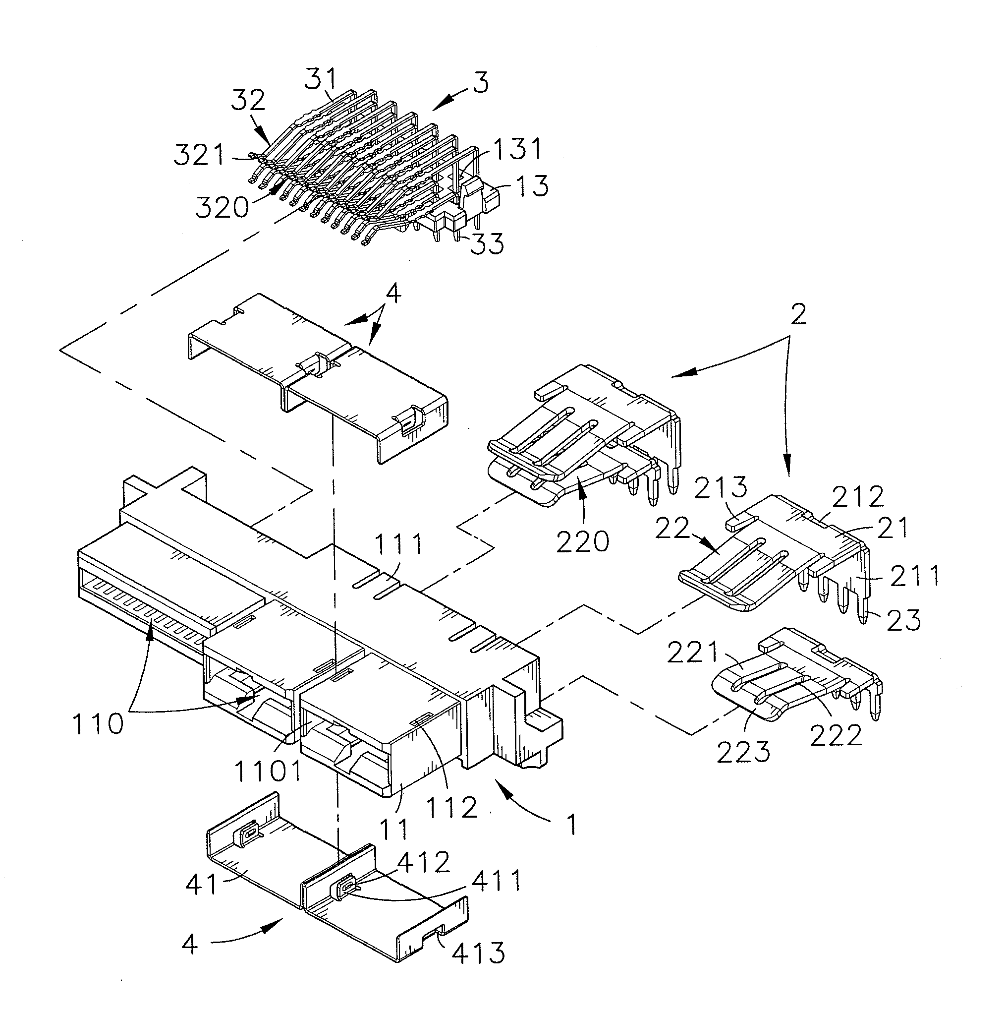
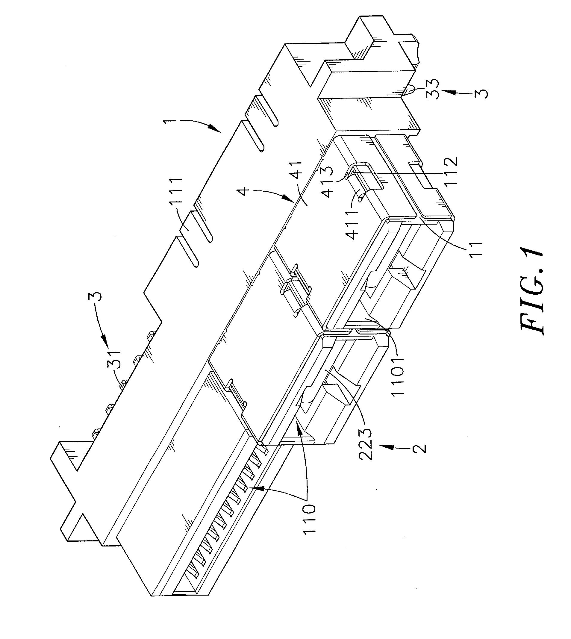
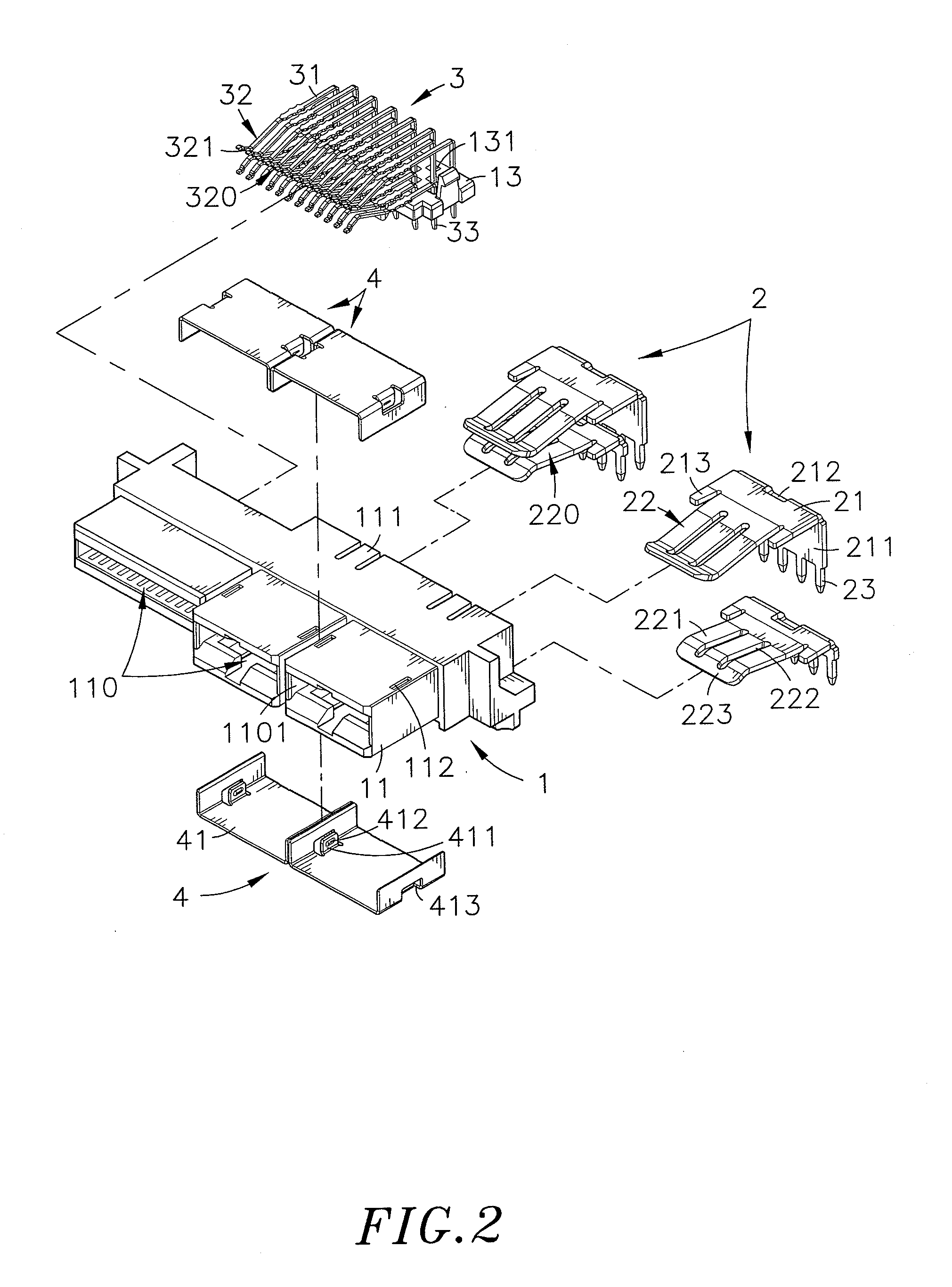
[0020]Referring to FIGS. 1, 2 and 3, an electrical power connector in accordance with the present invention is shown. The electrical power connector comprises an electrically insulative housing 1, and a plurality of conducting terminals 2.

[0021]The electrically insulative housing 1 comprises a plurality of mating portions 11 arranged in parallel at a front side thereof, a plurality of partition plates 12 disposed at a rear side thereof, an accommodation chamber 121 defined between each two adjacent partition plates 12 corresponding to one respective mating portion 11, a mating chamber 110 defined in each mating portion 11 and defining a front opening 1101 in communication with one respective accommodation chamber 121, two guide grooves 1102 bilaterally disposed in each mating chamber 110 between the associating front opening 1101 and accommodation chamber 121, and a plurality of springy hooks 111 extended from opposing top and bottom sides thereof and respectively suspending in top ...


PUM


Abstract

An electrical power connector includes an electrically insulative housing defining multiple front mating portions, multiple rear partition plates, an accommodation chamber between each two adjacent partition plates corresponding to one respective mating portion, a mating chamber in each mating portion and mounting holes on opposing top and bottom sides of the mating portions, pairs of conducting terminals respectively mounted in the accommodation chambers of the electrically insulative housing, and a heat dissipation mechanism including a plurality of thermal conductive metal plates fastened to the mounting holes of the electrically insulative housing with respective mounting lugs thereof and covered on the mating portions of the electrically insulative housing and for quick dissipation of heat.

Description

[0001]This application claims the priority benefit of Taiwan patent application number 100139404, filed on Oct. 28, 2011.BACKGROUND OF THE INVENTION[0002]1. Field of the Invention[0003]The present invention relates to electrical connector technology and more particularly, to an electrical power connector, which effectively reduces the operating conducting terminal impedance and temperature.[0004]2. Description of the Related Art[0005]When designing an electrical connector, a designer normally will pay attention to two basic parts, i.e., signal and power supply. When designing a signal circuit, a designer normally will not consider the factor of current variation for the reason that the applied current is normally low. However, with respect to the transmission of signals, a designer may consider the nature of the carrier (high frequency, low frequency) and many other factors (static interference, magnetic interference, impedance matching, etc.) without taking the factor of temperatur...

Claims


Application Information

Patent Timeline
Patent Type & Authority Applications(United States)
IPC IPC(8): H01R13/00
CPCH01R12/721H01R12/7088H01R12/724
Inventor CHIN, HSIEN-NINGTUAN, HAO-JAN
Owner ACES ELECTRONICS CO LTD
Why Eureka
Try Eureka