Aircraft ignition system and method of operating the same

a technology of aircraft ignition and ignition system, which is applied in the direction of hot gas positive displacement engine plants, machines/engines, jet propulsion plants, etc., can solve the problem of increasing the reliability of the system

Inactive Publication Date: 2013-05-09
CHAMPION AEROSPACE LLC
View PDF15 Cites 18 Cited by
  • Summary
  • Abstract
  • Description
  • Claims
  • Application Information

AI Technical Summary

Benefits of technology

[0006]In accordance with another aspect of the invention, there is provided an aircraft ignition system for use with a piston-power engine. The system may include an electrical circuit and a plurality of spark plugs. The electrical circuit may include a power circuit, a control circuit, and a discharge circuit. The power circuit may have two independent power sources—the first power source may include an aircraft bus and the second power source may include an alternator. The power circuit may be coupled to the control circuit, and the control circuit may have a plurality of engine sensors and a plurality of timing circuits. The power circuit also may be coupled to the discharge circuit, and the discharge circuit may have a plurality of charge pumps and a plurality of trigger circuits. In addition, each charge pump may drive a plurality of trigger circuits. The plurality of spark plugs may be located in different engine cylinders and coupled to the trigger circuits. The electrical circuit may operate in a first mode when the engine speed is within a first range of speeds and may operate in a second mode when the engine speed is within a second range of speeds.

Problems solved by technology

This redundancy increases the reliability of the system.

Method used


Image

  • Aircraft ignition system and method of operating the same
  • Aircraft ignition system and method of operating the same
  • Aircraft ignition system and method of operating the same

Examples


Embodiment Construction

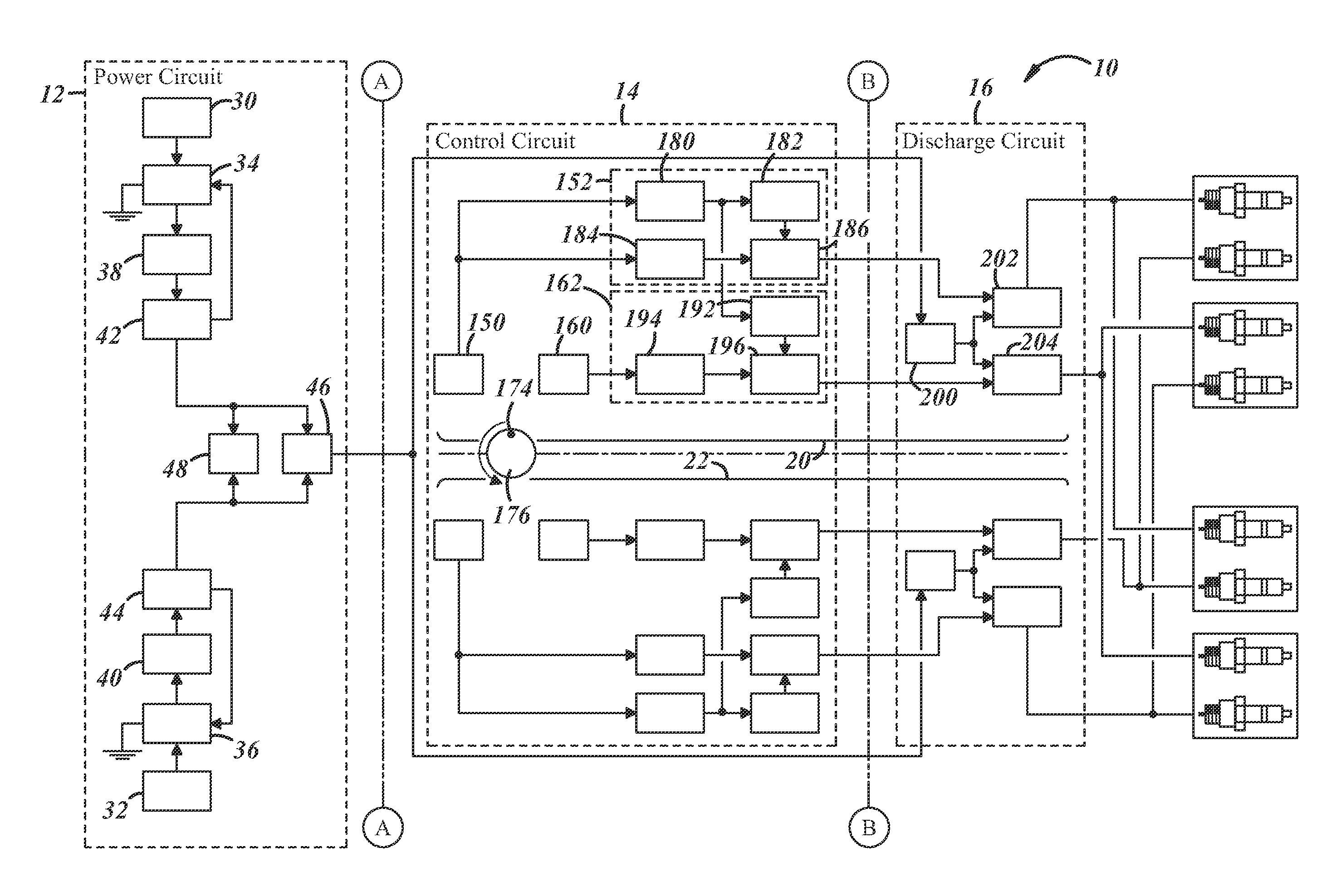
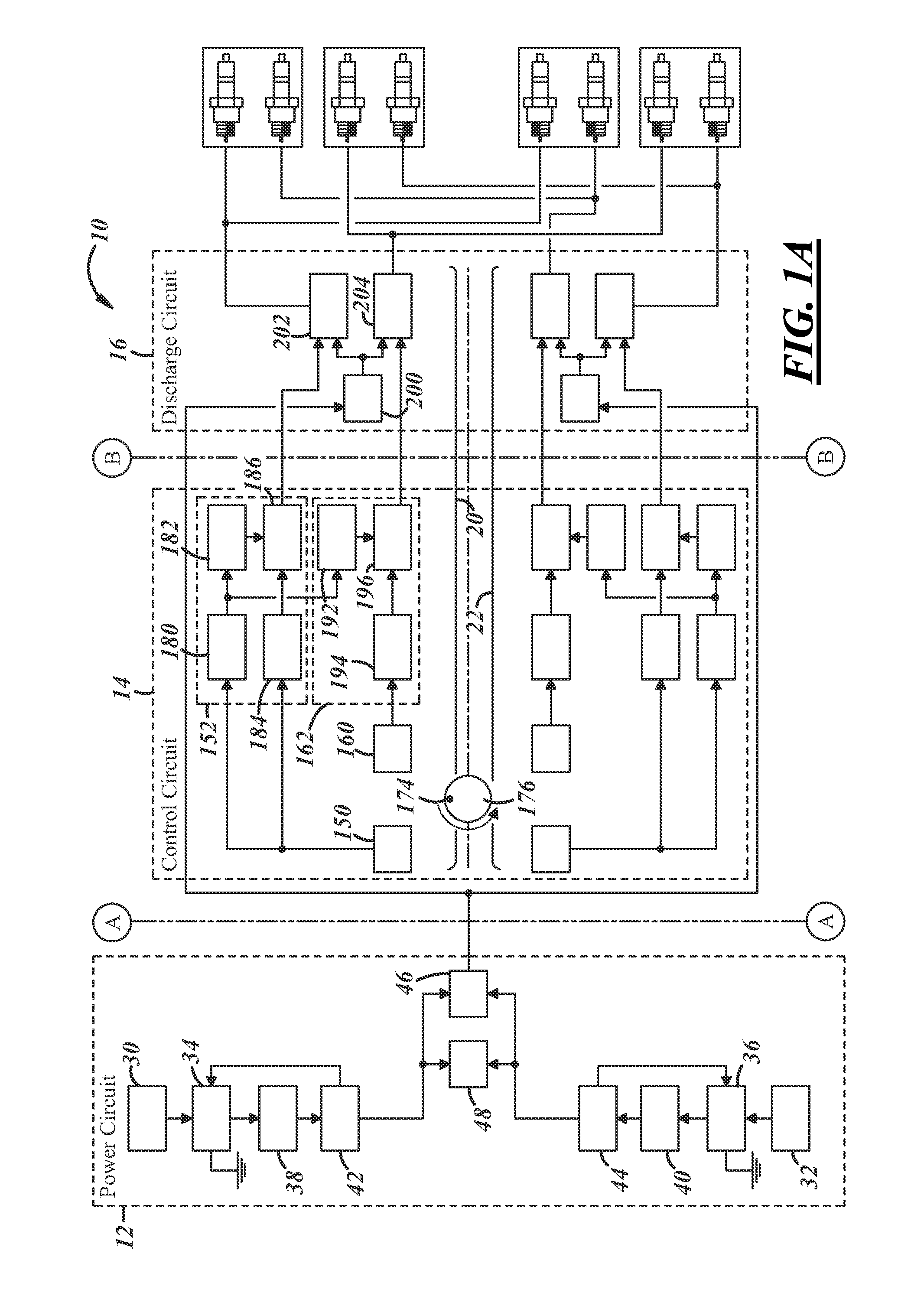
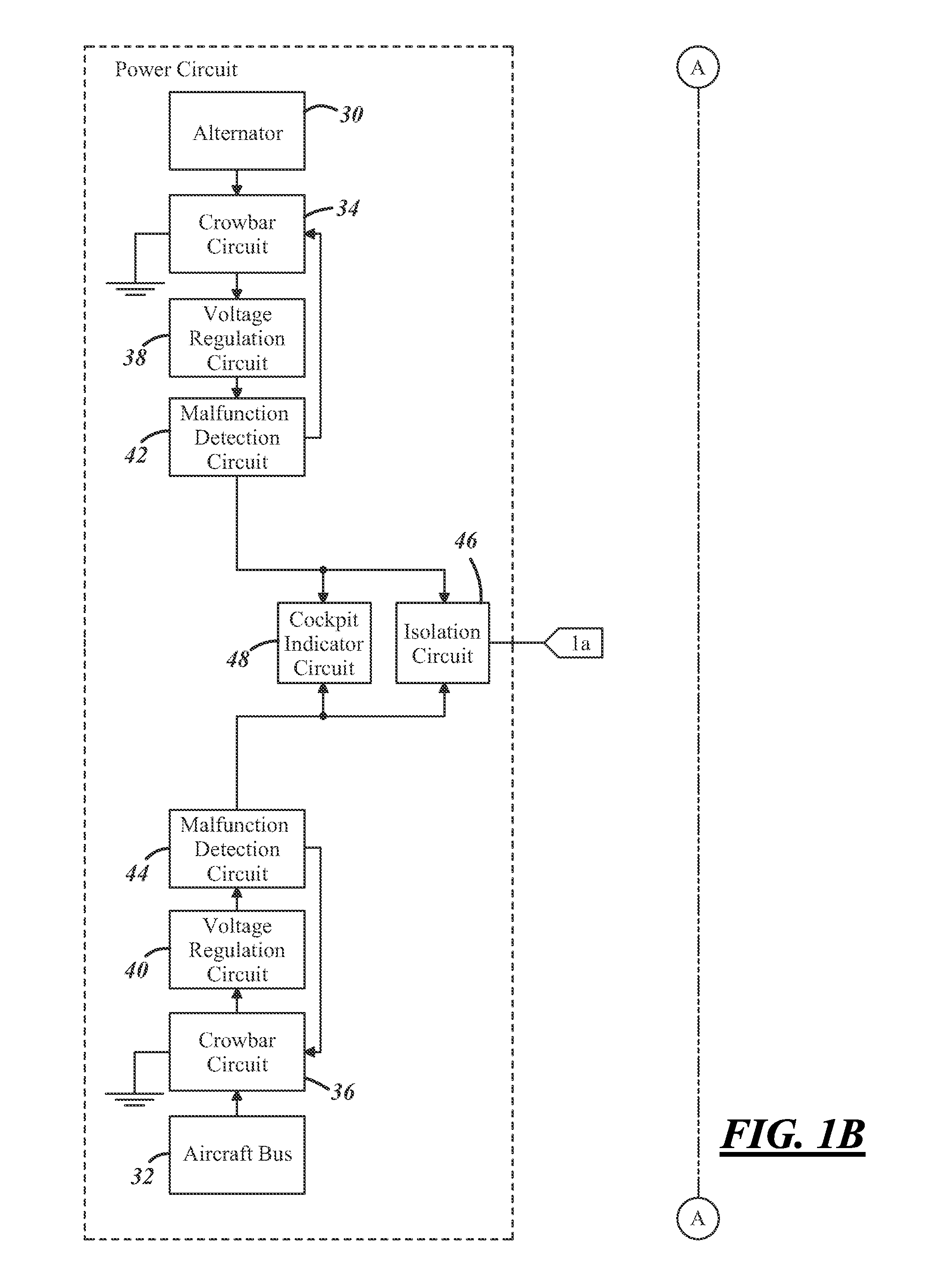
[0013]With reference to FIGS. 1A-1D, there is shown a block diagram of an exemplary aircraft ignition system 10 that includes a power circuit 12, a control circuit 14, and a discharge circuit 16. Generally speaking, aircraft ignition system 10 is a self-sustaining ignition system (SSIS) that uses redundant power sources to drive independent spark plugs in each of the cylinders of the engine. In an exemplary embodiment, aircraft ignition system 10 includes two separate and redundant power channels 20, 22, where each power channel provides electrical power over its own power delivery path and fires its own spark plugs. Although aircraft ignition system 10 is described below in the context of an exemplary four-stroke four-cylinder engine, it should be appreciated that the ignition system may be used with any aircraft utilizing an internal combustion or piston engine. This includes, for example, internal combustion engines having two, three, four, five, six or eight cylinders; engines t...


PUM


Abstract

An aircraft ignition system having a power circuit, a control circuit, and a discharge circuit and coupled to the spark plugs of an aircraft engine. The power circuit may include two independent power sources; e.g., alternator power (such as a permanent magnet alternator) and power from aircraft or DC power bus. The control circuit may control one or more aspects of the discharge circuit, e.g., the ignition timing. And the discharge circuit may trigger a capacitive discharge ignition event to the spark plugs.

Description

CROSS-REFERENCE TO RELATED APPLICATION[0001]This application claims the benefit of U.S. Provisional Patent Application No. 61 / 479,684, filed Apr. 27, 2011, the complete contents of which are hereby incorporated by reference.TECHNICAL FIELD[0002]This invention relates to aircraft ignition systems.BACKGROUND OF THE INVENTION[0003]Aircraft electrical power systems may include some degree of redundancy to protect against a single point failure. Power systems may include mission critical systems such as an ignition system that provides electrical power to fire the spark plugs used within a piston aircraft engine and that includes a control system to regulate the timing thereof. This redundancy increases the reliability of the system.SUMMARY OF THE INVENTION[0004]In accordance with one aspect of the invention, there is provided an aircraft ignition system having a power circuit which includes a first power source and a second power source, a control circuit, and a discharge circuit. The p...

Claims


Application Information

Patent Timeline
Patent Type & Authority Applications(United States)
IPC IPC(8): F02C7/266
CPCF05D2220/768F02C7/266
Inventor KEMPINSKI, STEVE J.
Owner CHAMPION AEROSPACE LLC
Why Eureka
Try Eureka