Rebalancing a main heat exchanger in a process for liquefying a tube side stream

a technology of liquefying and side stream, which is applied in the direction of liquefaction, indirect heat exchangers, lighting and heating apparatus, etc., can solve the problems of uneven temperature, and uneven heat transfer between the shell side and each of the first, second and third tube sides, etc., to achieve the effect of reducing pressur

Active Publication Date: 2013-05-09
LINDE AG
View PDF3 Cites 2 Cited by
  • Summary
  • Abstract
  • Description
  • Claims
  • Application Information

AI Technical Summary

Benefits of technology

[0030]In one form, the first tube side stream exchanges heat with a predominately liquid light refrigerant stream which is progressively boiled off on the shell side of the cold tube bundle. The evaporated refrigerant removed from the warm end of the shell side of the main heat exchanger may be fed to first and second refrigerant compressors in which the evaporated refrigerant is compressed to form a high pressure refrigerant stream. The high pressure refrigerant stream may be directed to a heat exchanger in which it is cooled so as to produce a partly-condensed refrigerant stream which is then directed in a separator to separate out a heavy refrigerant fraction in liquid form and a light refrigerant fraction in gaseous form. The heavy refrigerant fraction may become a second tube side stream which is supplied at the warm end of the warm tube bundle as a liquid and exits at the cold end of the warm tube bundle as a sub-cooled heavy refrigerant stream in liquid form. The sub-cooled heavy refrigerant stream removed at the cold end of the warm tube bundle may be expanded across a first expansion device to form a reduced pressure heavy refrigerant stream that is then introduced into the shell side of the main heat exchanger at a location intermediate between the cold end of the warm tube bundle and the warm end of the cold tube bundle, and wherein said reduced pressure heavy refrigerant stream is allowed to evaporate in the shell side, thereby cooling the fluids in the first, second and third tube side streams as they pass through the warm tube bundle.
[0031]A part of the light refrigerant fraction from the separator may become a third tube side stream which is introduced into the warm end of the warm tube bundle as a gas and exits at the cold end of the cold tube bundle as a sub-cooled liquid. The third tube side stream may be cooled from a gas to a liquid as it passes through the warm tube bundle and is cooled from a liquid to a sub-cooled liquid as it passes through the cool bundle. The sub-cooled light refrigerant stream removed from the cold end of the cold tube bundle may be expanded through a second expansion device to cause a reduction in pressure and produce a reduced pressure light refrigerant stream. The reduced pressure light refrigerant stream is introduced into the shell side of the main heat exchanger at its cold end, and wherein said reduced pressure light refrigerant stream is allowed to evaporate in the shell side, thereby cooling the fluids in the first and third tube side streams as they travel through the cold tube bundle as well as providing cooling to the fluids in the first, second and third tube side streams as they travel through the warm tube bundle.
[0032]In one form, the controller of the main heat exchanger of communicates with the mass flow adjustment means to reduce the first mass flow compared to the second mass flow when the first signal is higher than the second signal. In one form, the controller communicates with the mass flow adjustment means to reduce the second mass flow relative to the first mass flow when the first signal is lower than the second signal. In one form, the mass flow adjustment means is configured to adjust one or both of the first mass flow and the second mass flow to equalise the exit temperature of the first mass flow with the exit temperature of the second mass flow at the cold end of the main heat exchanger. In one form, the mass flow adjustment means is configured to adjust one or both of the first mass flow and the second mass flow to equalise the exit temperature of the first mass flow with the exit temperature of the second mass flow at the warm end of the main heat exchanger. In one form, the mass flow adjustment means comprises a first mass flow adjustment means for regulating the first mass flow.
[0033]In one form, the first mass flow adjustment means is a plug inserted in one or more individual tubes within the first subset of individual tubes to reduce the rate of the first mass flow relative to the rate of the second mass flow. In one form, the first mass flow adjustment means is a valve that restricts the first mass flow to one or more individual tubes within the first subset of individual tubes.
[0034]In one form, the mass flow adjustment means comprises a second mass flow adjustment means for regulating the second mass flow. In one form, the second mass flow adjustment means is a plug inserted in one or more of the individual tubes within the second subset of individual tubes to reduce the rate of the second mass flow relative to the rate of the first mass flow. In one form, the second mass flow adjustment means is a valve that restricts the second mass flow to one or more of the individual tubes within the second subset of individual tubes.

Problems solved by technology

As spiral-wound heat exchangers become larger to perform increased duties, it becomes increasingly difficult to distribute the shell side fluids evenly.
As a consequence, heat transfer between the shell side and each of the first, second and third tube sides may become uneven across the layers within the bundle.
This uneven distribution of temperature in the shell side fluids leads to unevenness in the temperature in portions of each of the tube side fluids at the cold ends of the bundle from each layer of tubes in the bundle, and for the shell-side fluid exiting at the warm end.
Such pinching causes a drop in efficiency of the main heat exchanger.
Any liquid present represents a significant loss of efficiency and must also be removed to avoid potential damage to the downstream refrigerant compression circuit.

Method used


Image

  • Rebalancing a main heat exchanger in a process for liquefying a tube side stream
  • Rebalancing a main heat exchanger in a process for liquefying a tube side stream
  • Rebalancing a main heat exchanger in a process for liquefying a tube side stream

Examples


Embodiment Construction

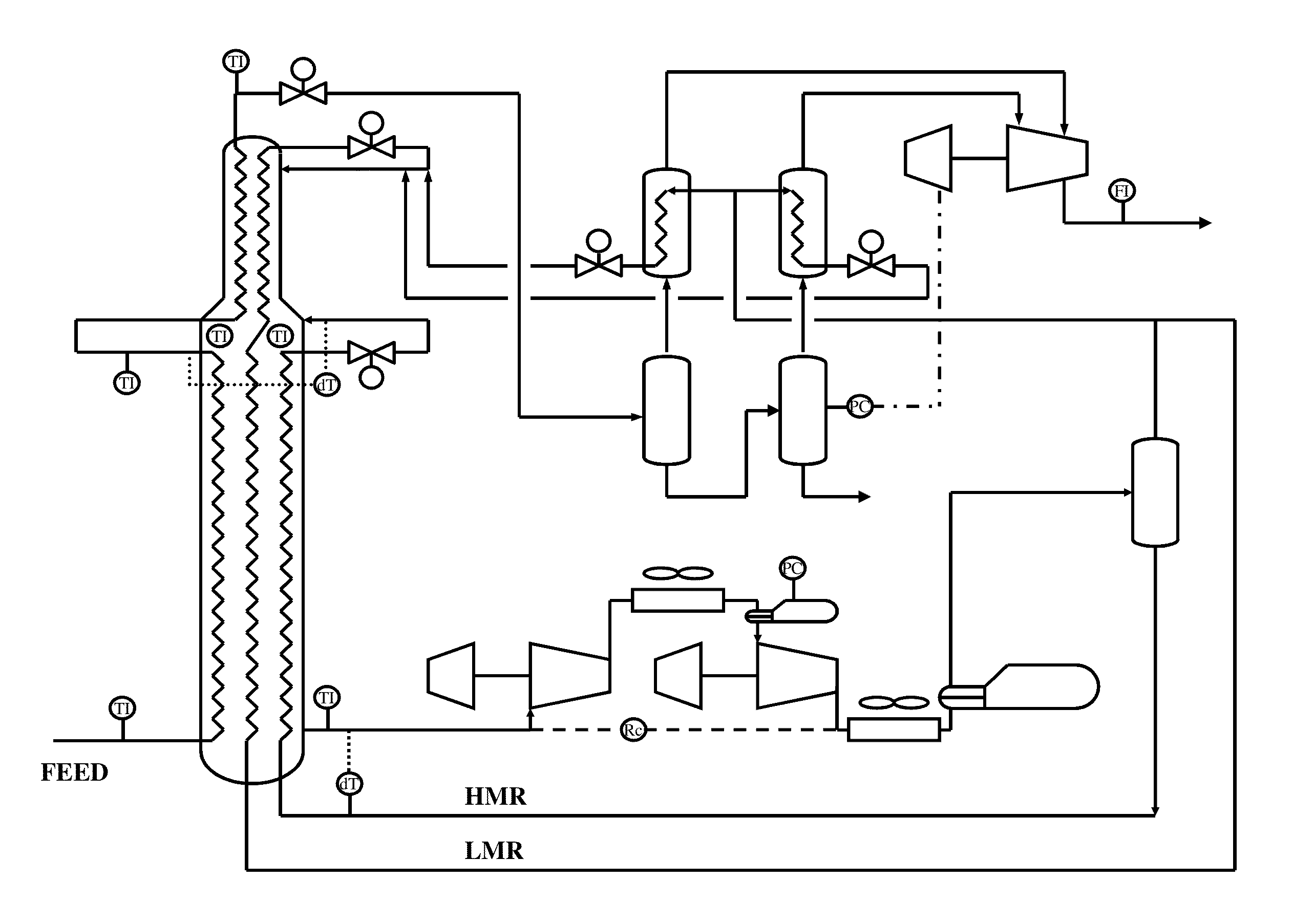
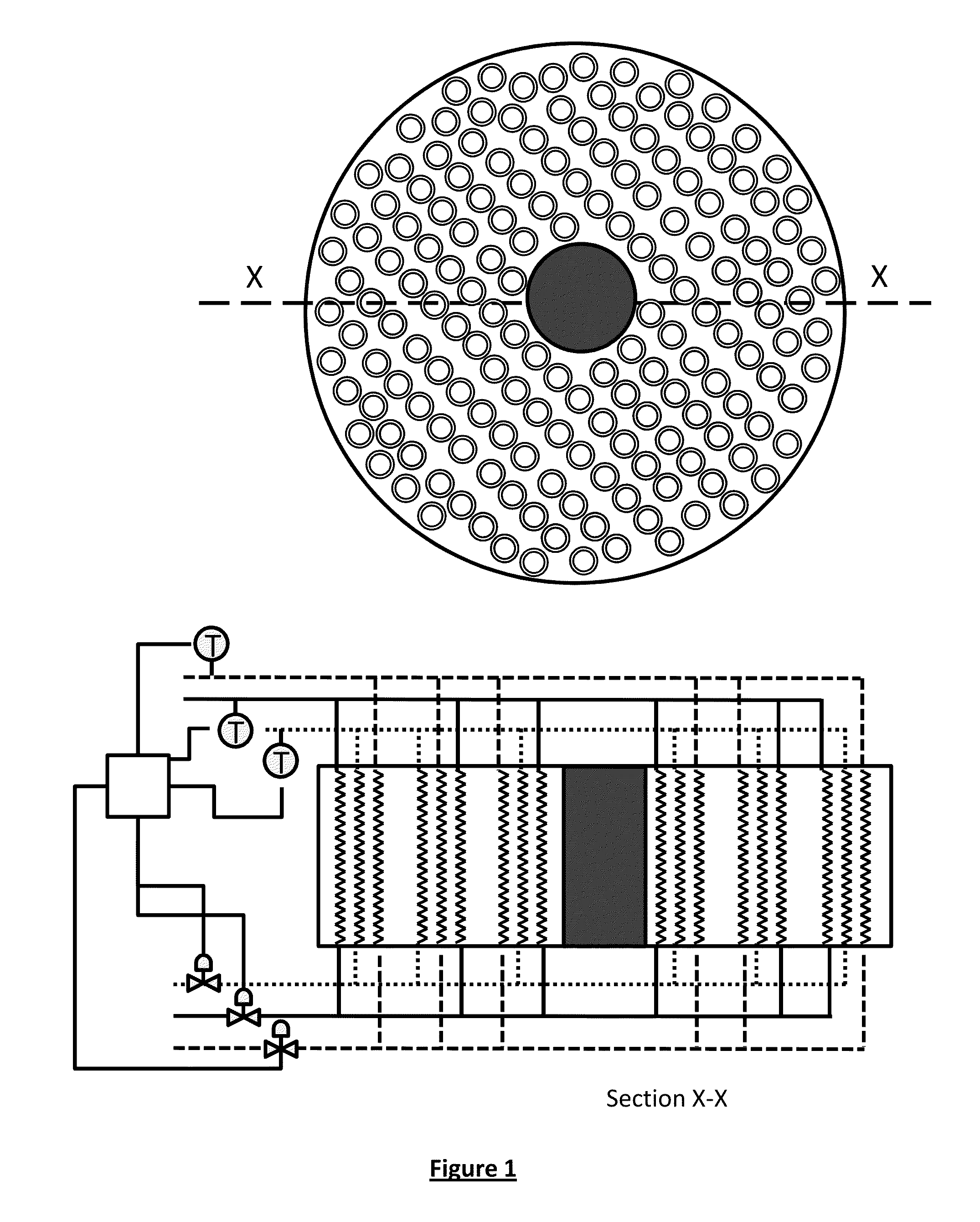
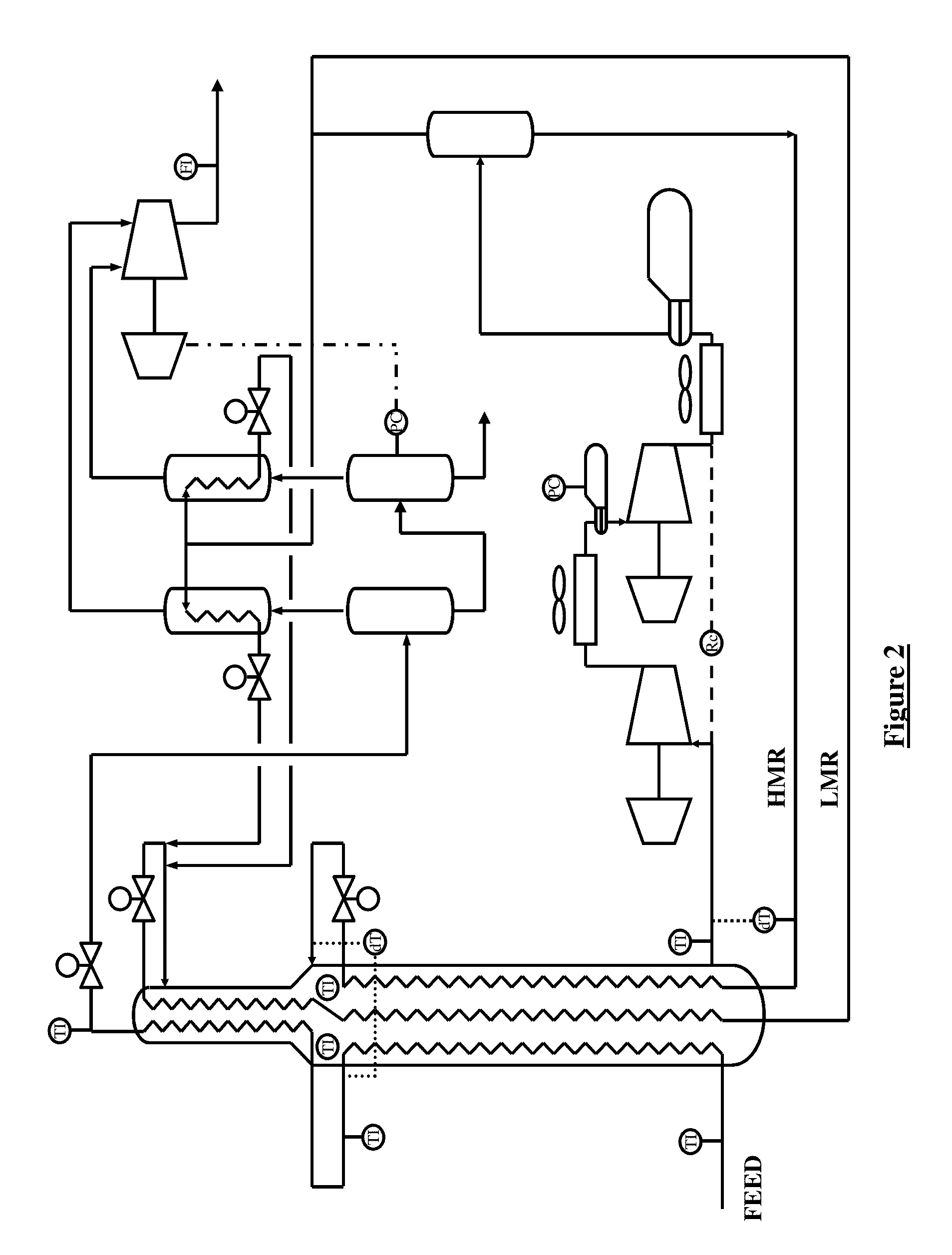
[0040]Particular embodiments of the process and apparatus of the present invention are now described, with particular reference to a plant for liquefying a gaseous, methane-rich feed gas in the form of natural gas in a main heat exchanger to produce liquefied natural gas, by way of example only. The present invention is equally applicable to a main heat exchanger used for other applications such as the production of ethylene or other plants for the thermal processing of at least two tube side streams. The terminology used herein is for the purpose of describing particular embodiments only, and is not intended to limit the scope of the present invention. Unless defined otherwise, all technical and scientific terms used herein have the same meanings as commonly understood by one of ordinary skill in the art to which this invention belongs. In the drawings, it should be understood that like reference numbers refer to like parts.

[0041]Using a typical prior art spiral wound main heat exc...


PUM


Abstract

A process for liquefying a tube side stream in a main heat exchanger is described. The process comprises the steps of: a) providing a first mass flow to the warm end of a first subset of individual tubes, b) providing a second mass flow to the warm end of a second subset of individual tubes, c) evaporating a refrigerant stream on the shell side; d) measuring an exit temperature of the first mass flow; e) measuring an exit temperature of the second mass flow; and, f) comparing the exit temperature of the first mass flow measured in step d) to the exit temperature of the second mass flow measured in step e), the process characterized in that at least one of the first and second mass flows is adjusted to equalise the exit temperature of the first mass flow with the exit temperature of the second mass flow.

Description

FIELD OF THE INVENTION[0001]The present invention relates to a process of liquefying a tube side stream to obtain a liquefied product by rebalancing the heat profile of a main heat exchanger. The present invention relates particularly though not exclusively to a process for liquefying a gaseous, methane-rich feed to obtain a liquefied product known as “liquefied natural gas” or “LNG”.BACKGROUND TO THE INVENTION[0002]A typical liquefaction process is described in U.S. Pat. No. 6,272,882 in which the gaseous, methane-rich feed is supplied at elevated pressure to a first tube side of a main heat exchanger at its warm end. The gaseous, methane-rich feed is cooled, liquefied and sub-cooled against evaporating refrigerant to get a liquefied stream. The liquefied stream is removed from the main heat exchanger at its cold end and passed to storage as liquefied product. Evaporated refrigerant is removed from the shell side of the main heat exchanger at its warm end. The evaporated refrigeran...

Claims


Application Information

Patent Timeline
Patent Type & Authority Applications(United States)
IPC IPC(8): F25J1/00F28D1/04
CPCF25J1/0022F25J1/0055F25J1/0244F25J1/0262F25J1/0267F25J2220/62F25J2290/32F28D7/024F28F13/00F28F13/08F28F27/02F28D1/0417F25J5/002F28D7/0066F25J2210/06F25J1/00F25J1/02F25J3/00F25J2290/60F25J1/0052F25J1/0254F28D7/16F28D7/0075F28F13/06
Inventor HODGES, DEREK WILLIAMKERBER, CHRISTIANESTEINBAUER, MANFREDHAMMERDINGER, MARKUS
Owner LINDE AG
Why Eureka
Try Eureka