Clutch device

Inactive Publication Date: 2013-05-09
ZF FRIEDRICHSHAFEN AG
View PDF3 Cites 21 Cited by
  • Summary
  • Abstract
  • Description
  • Claims
  • Application Information

AI Technical Summary

Benefits of technology

[0007]The invention relates to a clutch device having a first clutch element and a second clutch element, each rotationally supported on a common axis of rotation, and which, when in the engaged state, are coupled to one another in a form-locking manner by means of

Problems solved by technology

Moreover, the components in the two described actuation concepts are of considerable weight, and require a likewise not insignificant amount of space.
The latter

Method used


Image

  • Clutch device
  • Clutch device
  • Clutch device

Examples


Embodiment Construction

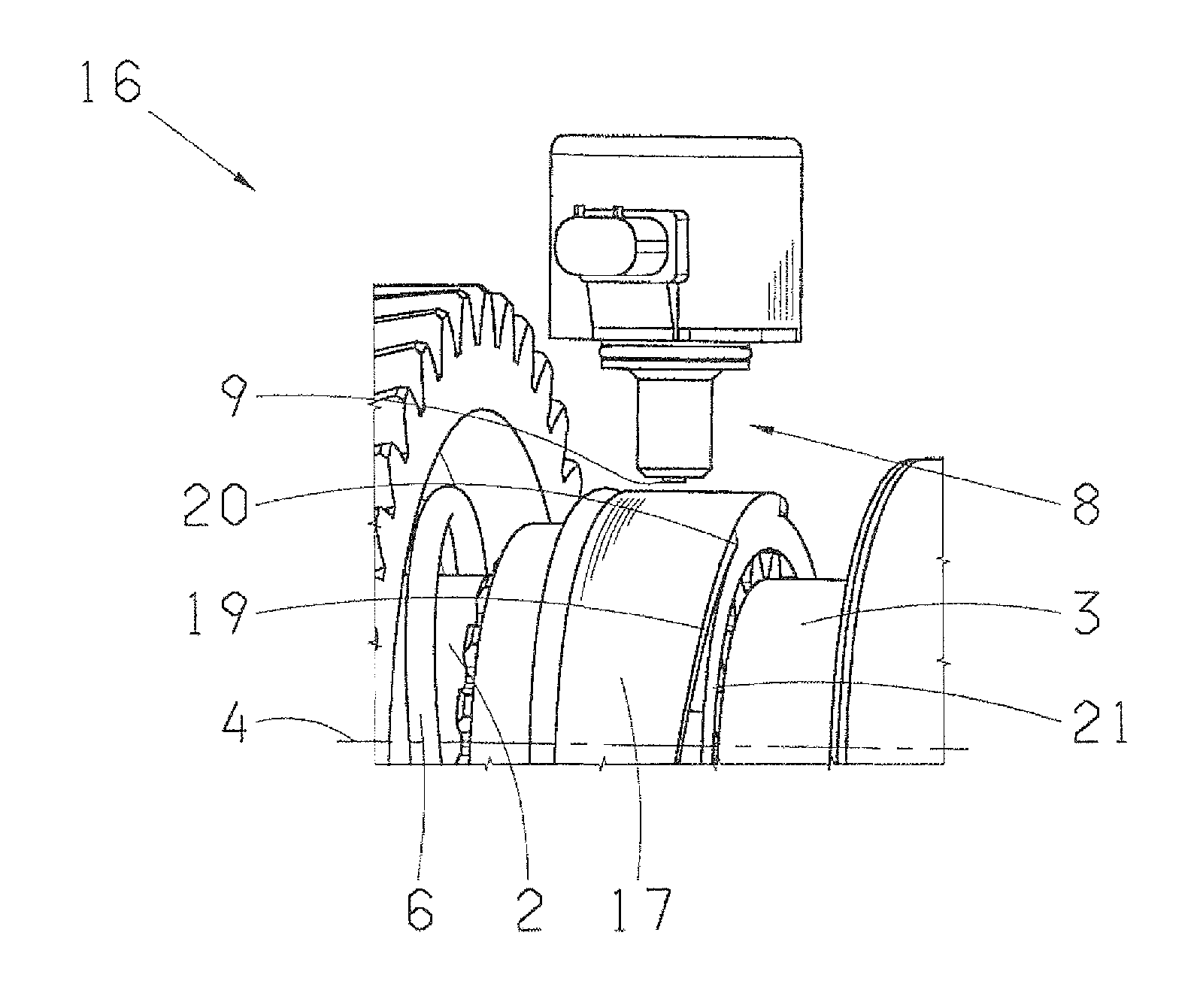
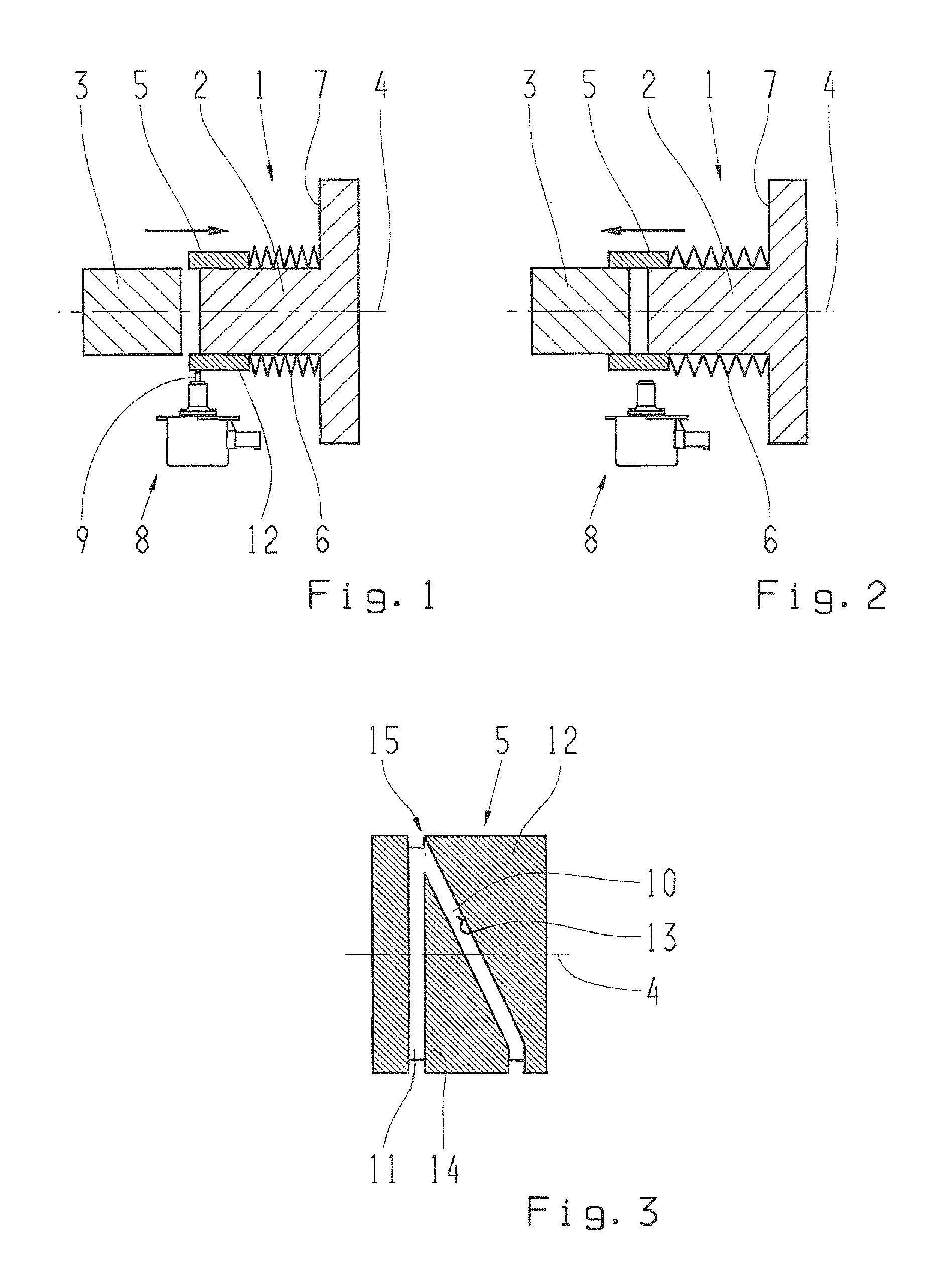
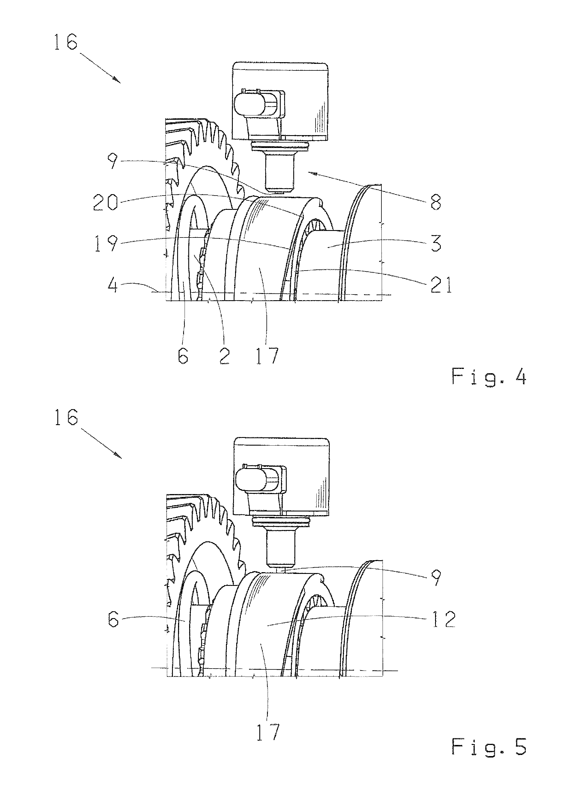
[0033]Corresponding parts are provided with the same reference symbols in FIGS. 1-16. Details of the embodiment examples explained in greater detail in the following can also represent an invention in and of themselves, or part of the subject matter of an invention.

[0034]An embodiment example is shown in FIGS. 1 and 2 of a clutch device 1 having a first clutch element 2 and a second clutch element 3 in a longitudinal section depiction. The clutch device 1 can, in particular, relate to a claw clutch. The two clutch elements 2 and 3 are each supported in a rotational manner on a common axis of rotation 4. They can be coupled to one another in a form-locking manner, by means of an axially, back and forth, displaceable, i.e. in the direction of the axis of rotation 4, sliding sleeve 5. The sliding sleeve 5 is disposed thereby, coaxially to the clutch elements 2, 3, i.e. the axis of rotation 4 of the clutch elements 2, 3 simultaneously forms the axis of rotation for the sliding sleeve 5,...


PUM


Abstract

The clutch device comprises a first clutch element and a second clutch element, which are each supported in a rotational manner on a common axis of rotation. In an engaged state, the clutch elements are coupled to one another in a form-locking manner by a sliding sleeve. The sliding sleeve is attached to the first clutch element in a rotationally fixed and axially displaceable manner. A peripheral surface of the sliding sleeve is provided with at least one step, having a first step flank and extending with a first step course on the peripheral surface of the sliding sleeve, wherein the first step course also has, at least in sections, at least one axial directional component in the direction of the axis of rotation. A placement agent can be displaced radially back and forth between an engaging placement agent position and a disengaging placement agent position, and is otherwise stationary.

Description

RELATED APPLICATIONS[0001]The present application claims priority to German Patent Application Number 10 2011 085 839.3, filed on Nov. 7, 2011, the entirety of which is hereby incorporated by reference herein.BACKGROUND OF THE INVENTION[0002]1. Field of the Invention[0003]The invention relates to clutch devices.[0004]2. Related Art[0005]A clutch device of this type is, for example, designed as a claw clutch. A claw clutch can be actuated hydraulically or with an electric motor. With a hydraulic actuation, a pump is needed to generate the hydraulic pressure, as well as valves and pistons that can be activated for displacing the claw in both directions, i.e. to the engaged state and to the disengaged state. With an electric motor actuation, no hydraulic components, such as lines and hydraulic seals, however, are necessary. Instead, an electric motor and other mechanical transmission components are needed in order, for example, to convert the rotational motion of the electric motor to ...

Claims


Application Information

Patent Timeline
IPC IPC(8): F16D11/14
CPCF16H63/304F16H2063/3056F16H2063/3093F16H63/18F16H2063/305F16D11/04F16D2023/123F16D23/12
Inventor GRANZOW, CLAUSSAITNER, MARTIN
Owner ZF FRIEDRICHSHAFEN AG
Why Eureka
Try Eureka