
Device and method for handling drops

a drop and drop technology, applied in the direction of fluid speed measurement, fluid pressure measurement by electric/magnetic elements, optical light guides, etc., can solve the problems of not being able to control the character, not being able to form facing drops using different flows of liquids, and not being able to achieve precise and reproducible forming, transfer of liquid from one surface to another,

Inactive Publication Date: 2013-05-09
COMMISSARIAT A LENERGIE ATOMIQUE ET AUX ENERGIES ALTERNATIVES
View PDF4 Cites 5 Cited by
  • Summary
  • Abstract
  • Description
  • Claims
  • Application Information

AI Technical Summary

Benefits of technology

The patent describes a device that can handle drops of liquid on different surfaces without direct contact between the liquid and the electrodes, which can cause electrolysis. The device uses a fluidic finger to prevent impact from other paths, allowing for separate manipulation of drops on different surfaces. This technology has applications in biological and chemical interactions.

Problems solved by technology

This characteristic cannot be controlled.
Likewise, this technique does not make it possible to form facing drops using different flows of liquids.
As such, this device does not make possible the transfer of a liquid from one surface to another or the precise and reproducible forming and handling of drops.

Method used


Image

  • Device and method for handling drops
  • Device and method for handling drops
  • Device and method for handling drops

Examples


first embodiment

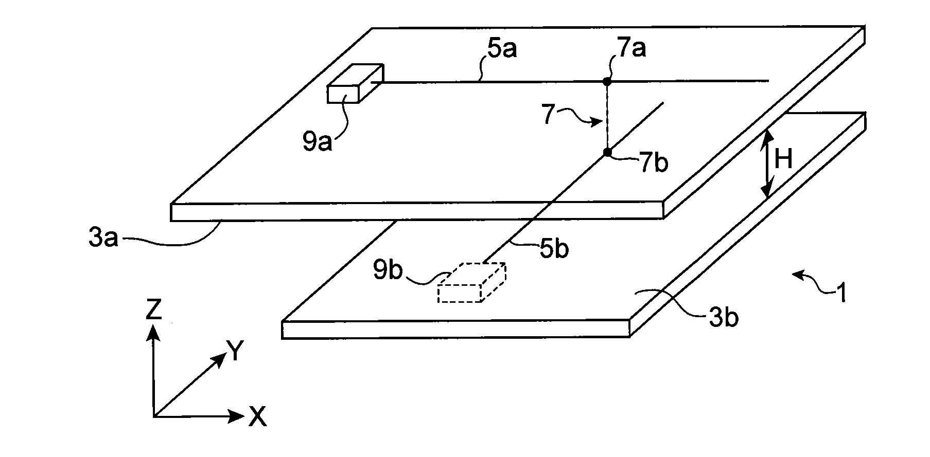
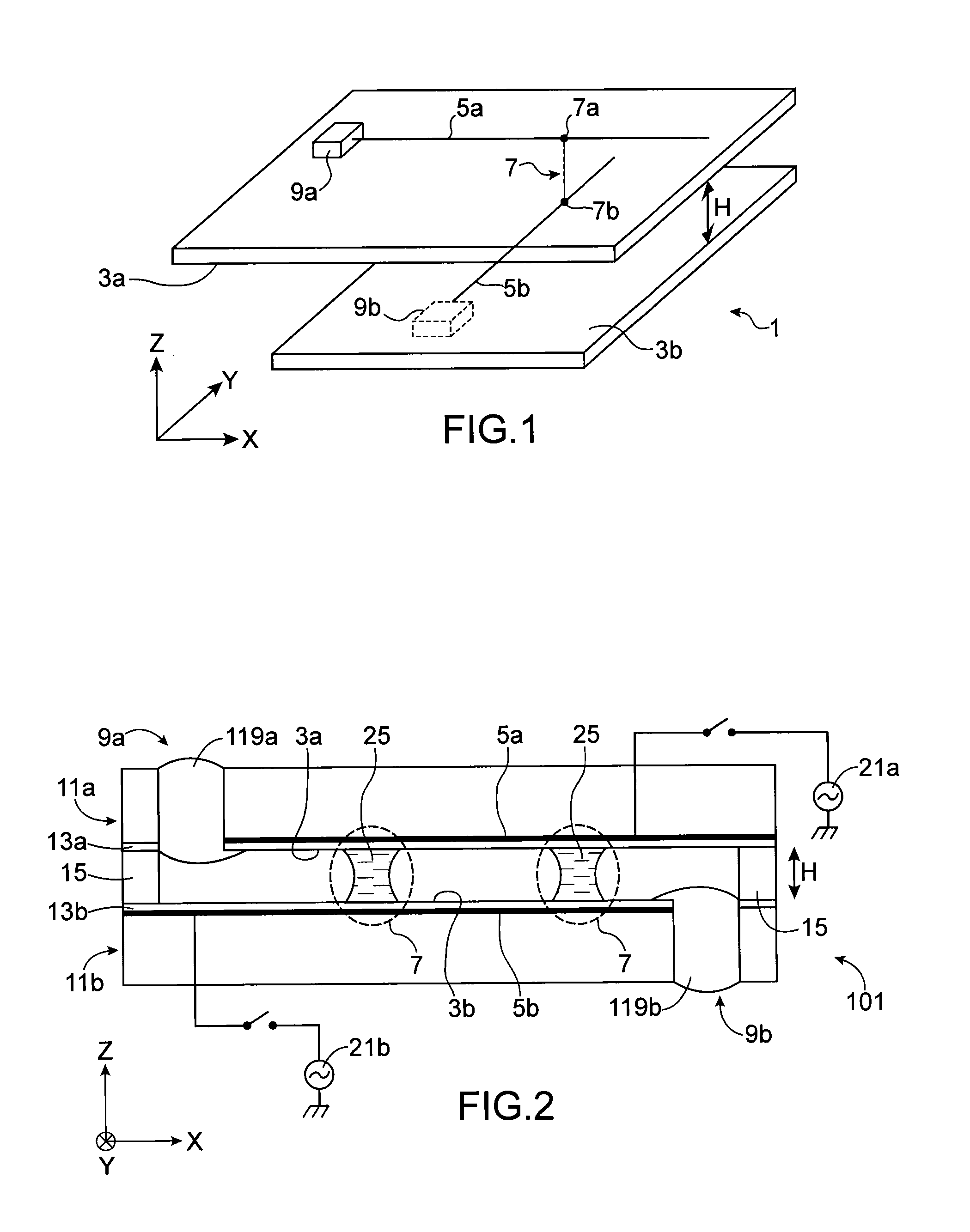
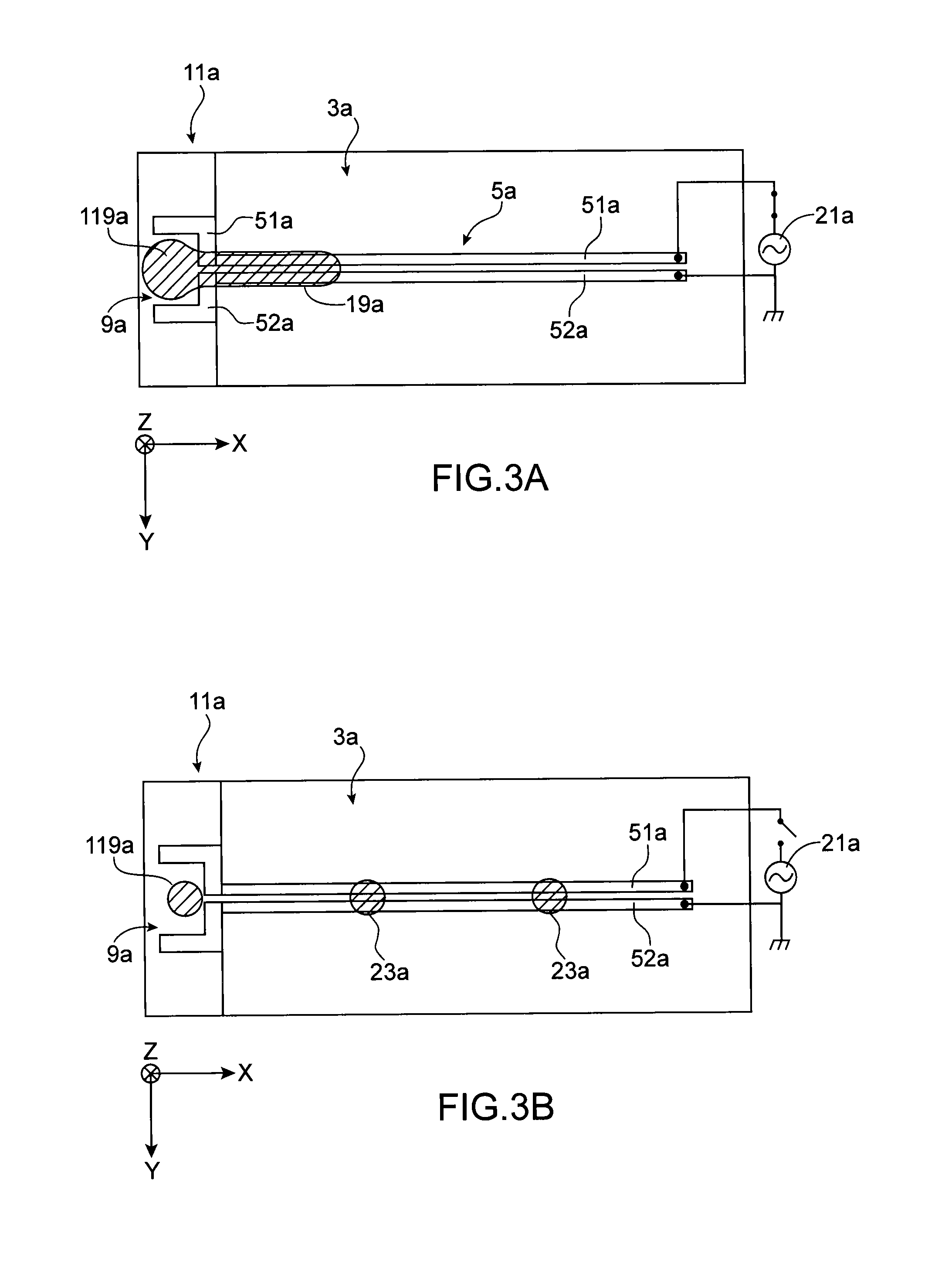
[0020]According to this invention, said first electrical displacement path comprising a pair of first electrodes substantially parallel and coplanar arranged on said first surface for the forming under the effect of the electrical activation, of a first fluidic finger from a first reservoir of a first liquid of interest, said second electrical displacement path comprising a pair of second electrodes substantially parallel and coplanar arranged on said second surface for the forming under the effect of the electrical activation, of a second fluidic finger from a second reservoir of a second liquid of interest, said first and second fluidic fingers rupturing via capillarity under the effect of the deactivation, by generating at least one respective first drop and at least one second drop which are mixed in said at least one crossover zone in order to form at least one global drop.

[0021]This makes it possible to cross the first and second fluidic fingers, without coming into contact, a...

second embodiment

[0030] said first electrical displacement path comprises a pair of substantially parallel and coplanar first electrodes arranged on said first surface for the forming through liquid dielectrophoresis under the effect of the electrical activation, of a fluidic finger from a reservoir of liquid of interest, said fluidic finger rupturing via capillarity under the effect of the deactivation, by generating at least one drop, said second electrical displacement path comprising second electrodes for the displacement of said at least one drop under the effect of an electrical activation of said second electrodes.

[0031]This makes it possible to form drops on a first surface, to transfer them onto another surface and to then displace them on this second surface in order to carry out various protocols for different biological and / or chemical applications.

[0032]Advantageously, the device comprises means of detecting a component of a drop formed on said at least one crossover zone.

[0033]This mak...


PUM

PropertyMeasurementUnit
widthaaaaaaaaaa
widthaaaaaaaaaa
conductivityaaaaaaaaaa

Abstract

The invention relates to a microfluidic device and a method for handling at least one drop.The device comprises first and second microfluidic surfaces (3a, 3b) parallel and separated from each other by a separation distance (H), at least one first electrical displacement path (5a) arranged on said first surface (3a), and at least one second electrical displacement path (5b) arranged on said second surface (3b). The at least one of the first and second paths is configured in order to form a respective fluidic finger along said path, said fluidic finger rupturing via capillarity, by generating at least one respective drop. The first and second paths are configured so that said separation distance between said first and second surfaces is on the one hand, greater than the fluidic thickness formed by each fluidic finger and, on the other hand, less than the fluidic thickness formed by each drop.

Description

TECHNICAL FIELD[0001]This invention relates to the general field of forming and handling drops in a microfluidic device.PRIOR ART[0002]In many fields, it is sought to form and handle drops for analysing liquid samples of small volumes in the simplest and least intrusive manner possible.[0003]This can be the case, for example, in order to establish biological and / or chemical interactions between two solutions for a chemical analysis, a biological or medical diagnosis, or in the field of agri-food or genetic engineering.[0004]For the purposes of illustration, biochips can be mentioned which constitute, in the field of molecular biology, microsystems for analysing the hybridisation of nucleic acids (DNA and / or RNA), or the interaction of the antigen / antibody, protein / ligand, protein / protein, enzyme / substrate, etc. type. It can then be sought to obtain the kinetic parameters or the equilibrium constants associated with these chemical and / or biological interactions.[0005]In general, the ...

Claims


Application Information

Patent Timeline
Patent Type & Authority Applications(United States)
IPC IPC(8): B81B1/00
CPCB01L3/502792B01L2400/0415B01L2400/0406B01L2300/0816
Inventor RENAUDOT, RAPHAELAGACHE, VINCENT
Owner COMMISSARIAT A LENERGIE ATOMIQUE ET AUX ENERGIES ALTERNATIVES
Learn More