Liquid ejecting head and liquid ejecting apparatus

a liquid ejecting apparatus and liquid ejecting technology, applied in the direction of printing, inking apparatus, etc., can solve problems such as defective discharge, and achieve the effect of reliable liquid ejecting apparatus

Inactive Publication Date: 2011-12-06
SEIKO EPSON CORP
View PDF15 Cites 2 Cited by
  • Summary
  • Abstract
  • Description
  • Claims
  • Application Information

AI Technical Summary

Benefits of technology

[0011]An advantage of some aspects of the invention is to provide a liquid ejecting head and a liquid injection apparatus which are able to prevent electrolysis of liquid caused by attachment of electrically conductive substances.
[0016]In this configuration, since the inner diameter of the liquid introduction hole at least on the side of the supporting substrate is set to be larger than the inner diameter of the case flow channel to form the shoulder portion between the case flow channel and the liquid introduction hole, and the insulating material is secured in the shoulder portion, the liquid flowing through the liquid introduction hole is prevented from coming into contact with the supporting substrate by the insulating material. Accordingly, in a case in which the diaphragm and the supporting substrate therearound are electrically short-circuited by foreign substances having electrical conductivity, occurrence of electrolysis of liquid between the liquid introduction hole of the supporting substrate and the periphery of the nozzle openings of a nozzle-formed plate is prevented. Consequently, problems such as defective discharge due to precipitation of components included in the liquid by electrolysis are prevented.
[0020]In this configuration, since the adhesive agent for joining the head case and the flow channel unit is used as the insulating material, it is not necessary to prepare additional insulating material and hence manufacture of the recording head is simplified.
[0023]In this configuration, since the liquid ejecting which is able to prevent defective discharge due to the electrolysis of liquid is mounted, a reliable liquid ejecting apparatus is provided.

Problems solved by technology

However, since the diaphragm is exposed into the storage chamber through the opening on the bottom surface of the head case, there is a case in which foreign substances such as machining chips enter into the storage chamber during the recording head assembly process, and drop onto the diaphragm.
When such electrolysis proceeds, the components in ink such as pigment is precipitated around the ink introducing hole and sludge may clog the flow channels or the nozzle openings and cause defective discharge.

Method used


Image

  • Liquid ejecting head and liquid ejecting apparatus
  • Liquid ejecting head and liquid ejecting apparatus
  • Liquid ejecting head and liquid ejecting apparatus

Examples


Embodiment Construction

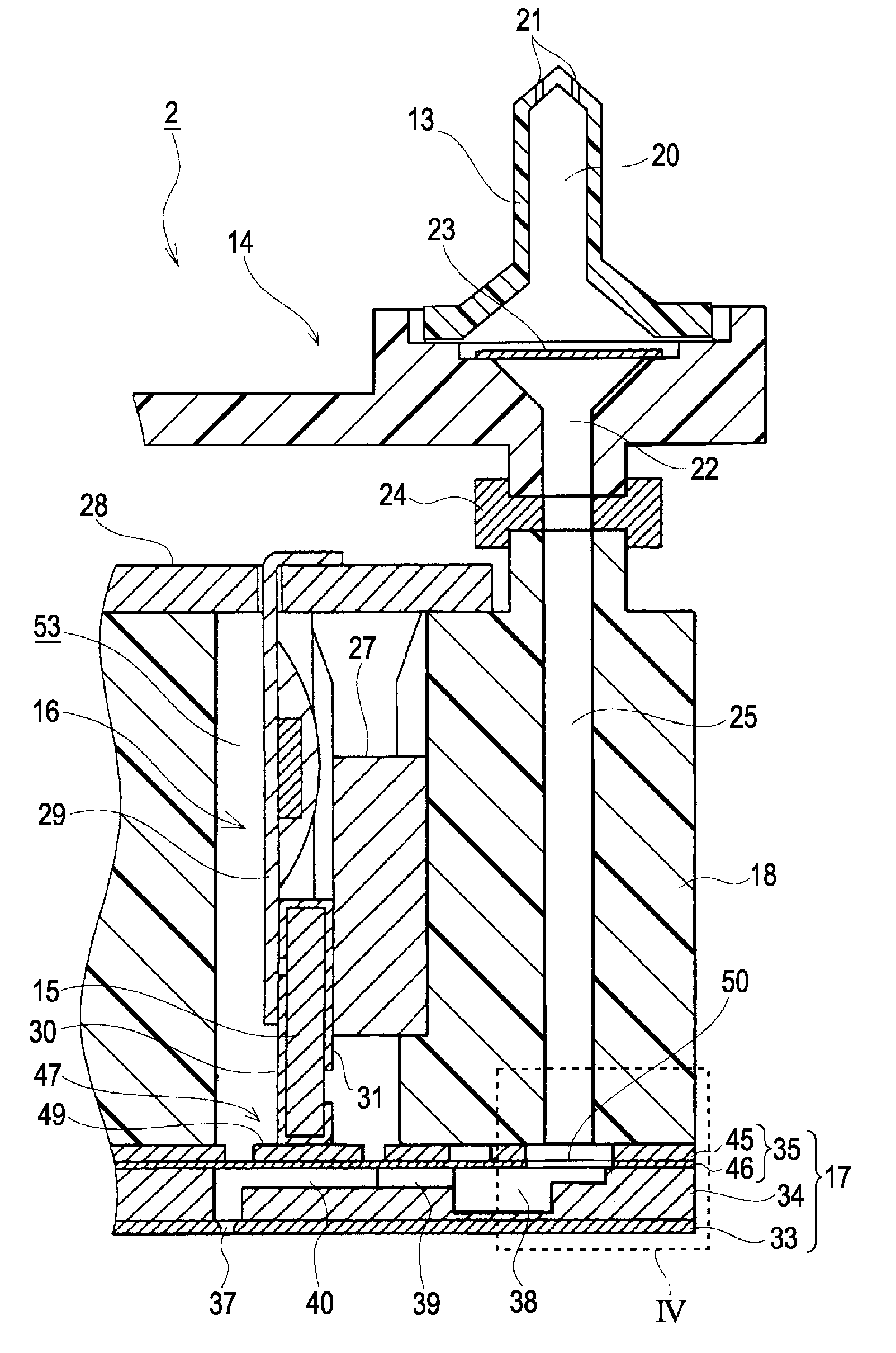
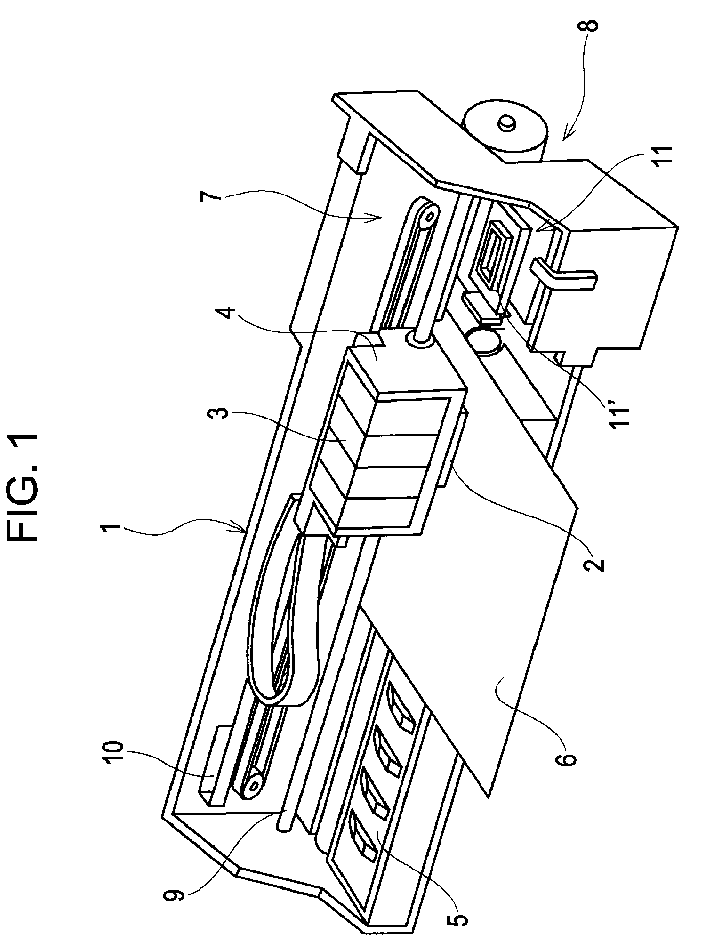
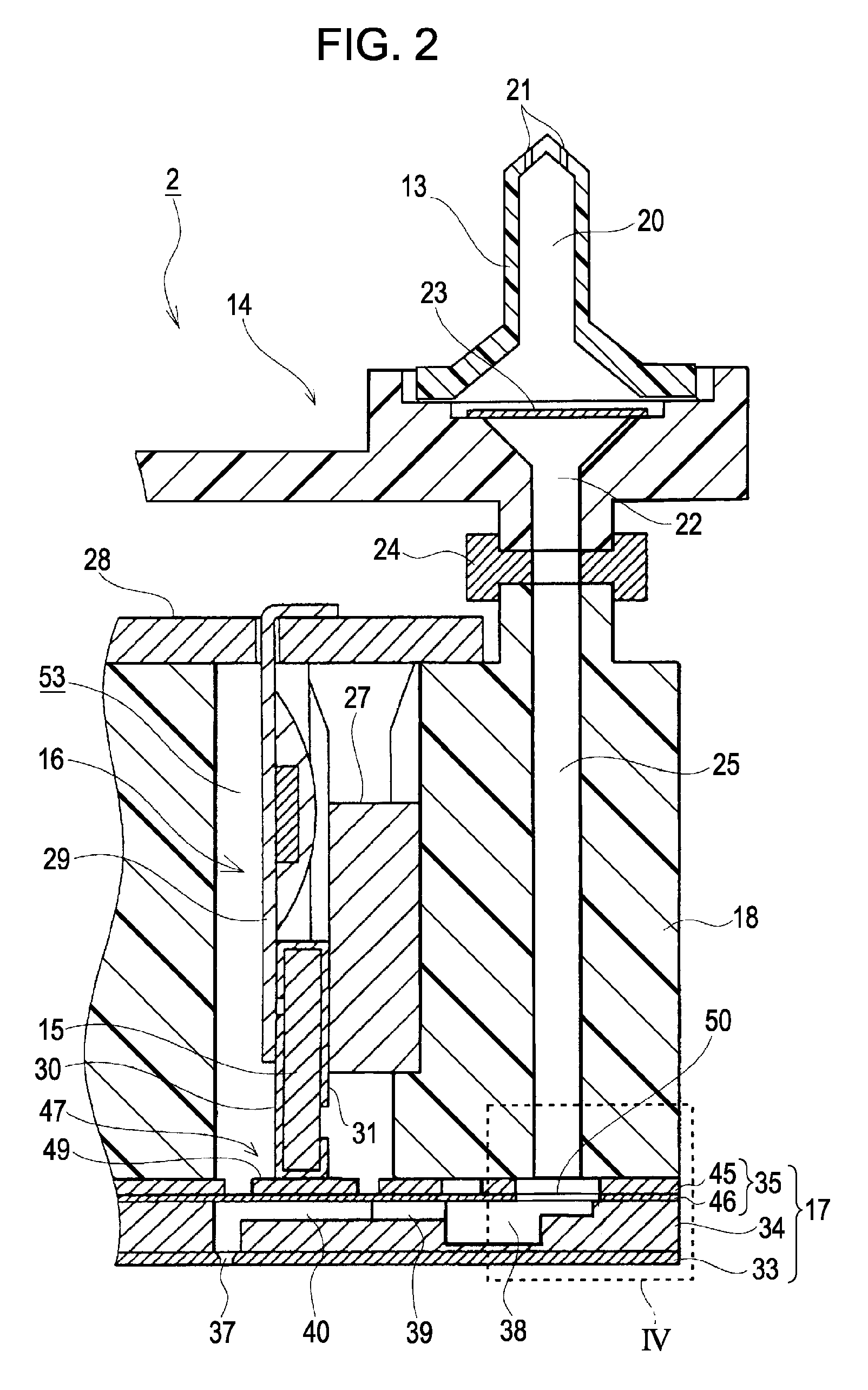
[0031]Referring now to the attached drawings, exemplary embodiments of the invention will be described below. In the embodiments shown below, although various limitations are given as an preferred embodiment of the invention, the scope of the invention is not limited to these embodiments unless otherwise specified. In the description shown below, an inkjet printer (hereinafter, referred to as printer) shown in FIG. 1 is exemplified as the liquid ejecting apparatus of the invention.

[0032]A printer 1 roughly includes a carriage 4 that has a recording head 2 as a sort of liquid ejection head mounted thereon and an ink cartridge 3 as a sort of liquid storage member detachably mounted thereon, a platen 5 disposed below the recording head 2 for transporting recording paper 6 (a sort of discharged object), a carriage transfer mechanism 7 that transfers the carriage 4 in the paper width direction of the recording paper 6. The term “paper width direction” in this case means the primary scann...


PUM


Abstract

A liquid ejecting head includes: a flow channel unit including a flow-channel-formed substrate that defines liquid flow channels including pressure chambers communicating with nozzle openings and a sealing plate formed with a diaphragm that varies the capacities of the pressure chambers and a liquid introduction hole, the sealing plate being joined to the flow-channel-formed substrate and defining lines of liquid flow channels including pressure chambers; and a head case including a storage chamber that accommodates a pressure generator for displacing the diaphragm and a case flow channel for supplying liquid to the liquid flow channel of the flow channel unit, the diaphragm being arranged at an opening of the storage chamber on the bottom surface side and the flow channel unit being joined to the head case in a state in which the case flow channel and the liquid flow channel are communicated with each other via the liquid introduction hole, and the sealing plate is formed of a composite plate member formed by adhering an electrically conductive supporting substrate which is joined to the head case and an insulative elastic film joined to the flow-channel-formed substrate to each other, the inner diameter of the liquid introduction hole at least on the side of the supporting substrate is set to be larger than the inner diameter of the case flow channel to form a shoulder portion between the case flow channel and the liquid introduction hole, and an insulating material is secured in the shoulder portion.

Description

[0001]The entire disclosure of Japanese Patent Application No. 2007-46101, filed Feb. 26, 2007 is expressly incorporated by reference herein.BACKGROUND[0002]1. Technical Field[0003]The present invention relates to an liquid ejecting head such as an ink jet recording head and a liquid ejecting apparatus and, more specifically, to a liquid ejecting head including a flow channel unit which defines lines of liquid flow channels extending from a common liquid chamber through pressure chambers to nozzle openings and being capable of discharging liquid from the nozzle openings as liquid drops by driving a pressure generator and a liquid ejecting apparatus having the same.[0004]2. Related Art[0005]Examples of a liquid ejecting head that generates pressure variations in liquid in a pressure chambers to cause the liquid to be discharged from nozzle openings as liquid drops include inkjet recording heads used for image recording apparatuses such as printers, color material ejecting heads used ...

Claims


Application Information

Patent Timeline
Patent Type & Authority Patents(United States)
IPC IPC(8): B41J2/135B41J2/17B41J2/045
CPCB41J2/14233B41J2002/14362B41J2002/14419B41J2202/03
Inventor OKAZAWA, NORIAKIAKAHANE, FUJIO
Owner SEIKO EPSON CORP
Why Eureka
Try Eureka