Safety circuit arrangement for connection or failsafe disconnection of a hazardous installation

a safety circuit and hazardous installation technology, applied in the direction of relays, electrical equipment, basic electric elements, etc., can solve the problems of increasing complexity, significant set-up effort, intentional overruling of protective measures, etc., and achieve the effect of less expensiv

Active Publication Date: 2013-05-09
PILZ (COMPANY)
View PDF1 Cites 9 Cited by
  • Summary
  • Abstract
  • Description
  • Claims
  • Application Information

AI Technical Summary

Benefits of technology

[0019]Known safety circuit arrangements generally use a signal loop from the control device to the signaling device and back again. This entails the risk of a cross connection between the forward line and the return line of the signal loop, with such cross connection bridging the signaling device and erroneously suggesting a safe state to the control device. The novel safety circuit arrangement dispenses with the loop and thus avoids a potential source of error in known safety circuit arrangements. Secondly, the novel signaling device generates a dynamic signal with a plurality of signal pulses, with the result that a “stuck-at” fault in the signaling device or at the cores of the two-wire line is quickly detected. The combination of the two features makes it possible to connect the signaling device and the control device to one another in a failsafe manner via a merely two-core cable. The novel safety circuit arrangement is therefore perfectly suited for applications in which the number of available line cores is limited. However, even when more line cores are generally available, the novel safety circuit arrangement can advantageously be used since the wiring complexity between the signaling device and the control device is minimized.
[0037]In this refinement, the failsafety of the signaling device is “made” in the control device, i.e. the decision as to whether a fault state is present or not and the response to a possible fault of the signaling device takes place in the control device. The pulsed signal is therefore per se not necessarily a “safe” signal. Only the interpretation of the pulsed signal in the control device, in particular the comparison with the expectations stored in the control device, makes it possible to say whether there is a fault. The refinement enables a very inexpensive implementation since fault detection mechanisms are required in the control device in any case. The signaling device can have a simpler and therefore less expensive embodiment.

Problems solved by technology

However, there are also cases in which protective measures are intentionally overridden, for example in order to allow a machine setup operating mode while the protective door is open.
The individual signaling devices / sensors can be located far away from one another, which results in considerable set-up effort.
Therefore, the connecting lines between signaling devices / sensors and control devices of a safety circuit arrangement often have redundancy, which additionally increases the complexity.
Such an implementation is therefore still complex, despite the already achieved advantages, in particular when it is necessary to bridge large distances between individual signaling devices and the control device.
When controlling ski lifts, for example, there may be distances of several kilometers between a signaling device and the control device and in such cases it is desirable to use already existing lines, although there are generally not sufficient line cores available for an implementation according to DE 10 2004 020 997 A1.
Nevertheless, a cross-connection between the line at the enable signal output of the control device and the line at the enable signal input of the control device cannot readily be detected, with the result that further redundant signal lines may be required for a higher safety category.
The single-channel connection does not per se provide any failsafety and is only proposed for a start button, which in such cases is typically arranged close to the hazardous installation.
For a safety circuit arrangement of the type mentioned at the outset, both the control device and the signaling device need to have an ASI bus-compatible interface module, which is too complex and expensive for some applications.

Method used


Image

  • Safety circuit arrangement for connection or failsafe disconnection of a hazardous  installation
  • Safety circuit arrangement for connection or failsafe disconnection of a hazardous  installation
  • Safety circuit arrangement for connection or failsafe disconnection of a hazardous  installation

Examples


Embodiment Construction

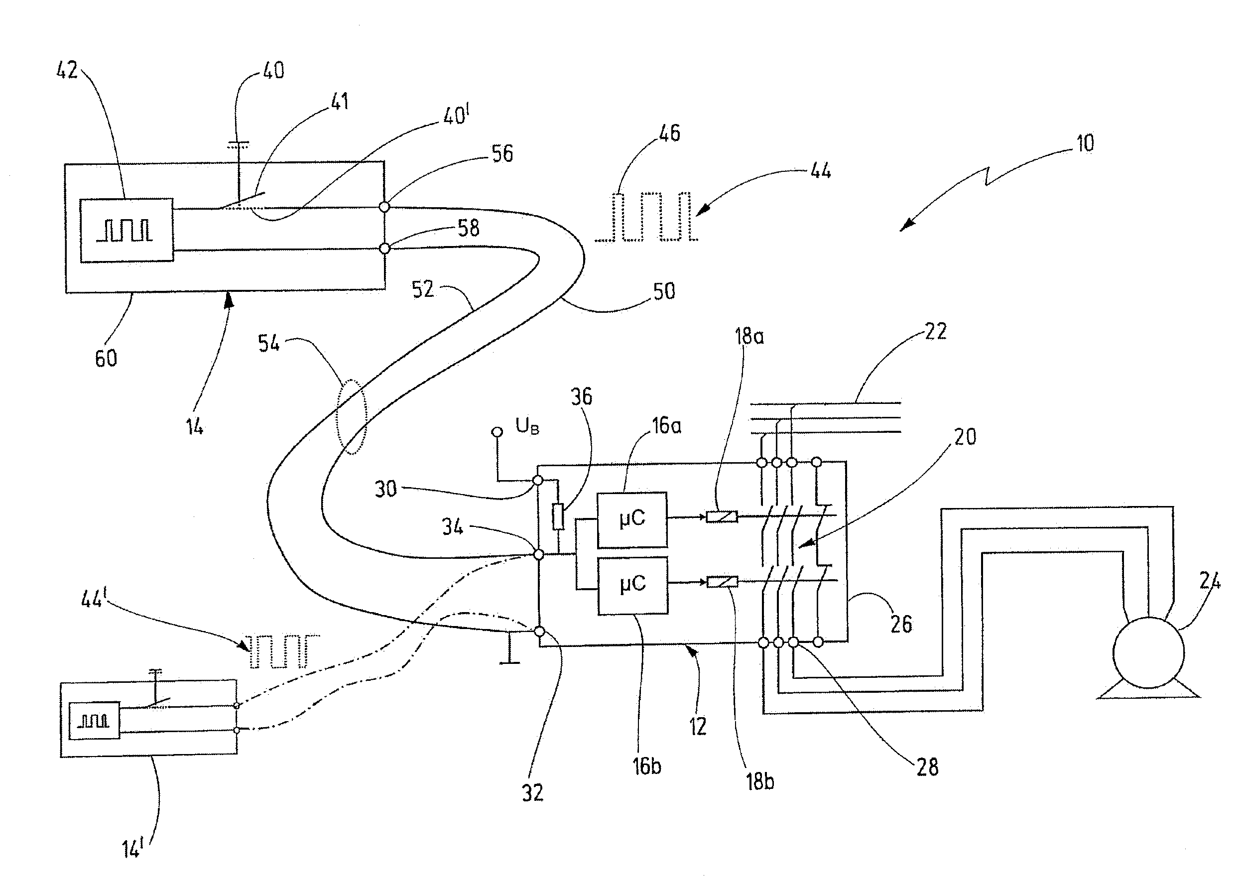
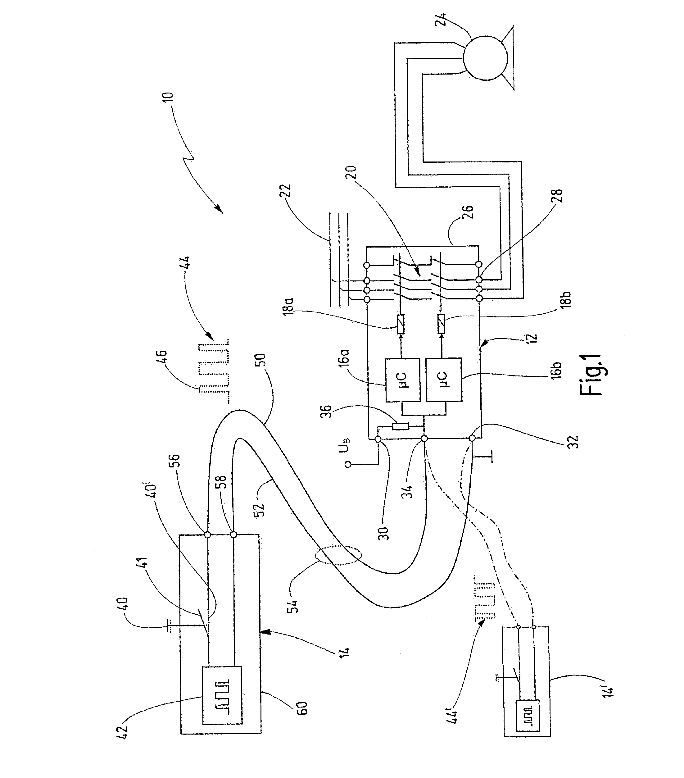
[0042]In FIG. 1, an exemplary embodiment of the novel safety circuit arrangement is denoted by the reference numeral 10 in its entirety. The safety circuit arrangement 10 comprises a control device 12 and a signaling device 14. In this exemplary embodiment, the control device 12 is a safety switching device with a largely fixed functional range. Suitable safety switching devices are offered for sale by the applicant under the brand name PNOZ®. The safety switching device 12 is designed to process input signals from signaling devices in order to connect or disconnect an actuator, such as a contactor, a solenoid valve or an electric drive, for example, depending on said input signals. As an alternative to a safety switching device, the control device 12 could be a programmable safety controller, as is offered for sale by the applicant under the brand name PSS® in different variants.

[0043]The control device 12 has multiple-channel redundancy and includes test functions which are design...


PUM


Abstract

A safety circuit arrangement for failsafe connection or disconnection of a hazardous installation has a control device, which is designed to connect or interrupt, in failsafe fashion, a power supply path to the installation. The safety circuit arrangement also has a signaling device, which is connected to the control device via a two-wire line having a first core and a second core. The signaling device has an actuator, which can change between a defined first state and a second state. Between the two cores is a substantially constant voltage when the actuator is in the second state. A pulse generator in the signaling device causes a voltage dip between the first core and the second core in order to generate a defined pulsed signal comprising a plurality of signal pulses on the lines, when the actuator is in the defined first state.

Description

CROSSREFERENCES TO RELATED APPLICATIONS[0001]This application is a continuation of international patent application PCT / EP2011 / 060444 filed on Jun. 22, 2011 designating the U.S., which international patent application has been published in German language and claims priority from German patent application DE 10 2010 025 675.7 filed on Jun. 25, 2010. The entire contents of these prior applications are incorporated herein by reference.BACKGROUND OF THE INVENTION[0002]The present invention relates to a safety circuit arrangement for connection or failsafe disconnection of a hazardous installation, and to a new type of signaling device used in such a safety circuit arrangement.[0003]A safety circuit arrangement in terms of the present invention is a circuit arrangement with at least two components, which interact so as to protect against hazardous operation of a technical installation, i.e. so as to avoid accidents which endanger the health or the life of people in the vicinity of the i...

Claims


Application Information

Patent Timeline
Patent Type & Authority Applications(United States)
IPC IPC(8): H02H11/00
CPCH01H47/005
Inventor PULLMANN, JUERGENZINSER, CHRISTOPHSCHLECHT, MICHAEL
Owner PILZ (COMPANY)
Why Eureka
Try Eureka