Device, method and program for determining obstacle within imaging range during imaging for stereoscopic display

a technology of determining method and imaging range, which is applied in the field of devices, methods and programs for determining obstacles within imaging range during imaging for stereoscopic display, can solve the problems of only applicable determining method, operator viewing live-view image cannot recognize, and is not easy to visually recognize, so as to achieve higher and more stable accuracy, the effect of higher accuracy and higher accuracy

Inactive Publication Date: 2013-05-09
FUJIFILM CORP
View PDF3 Cites 72 Cited by
  • Summary
  • Abstract
  • Description
  • Claims
  • Application Information

AI Technical Summary

Benefits of technology

[0010]In view of the above-described circumstances, the present invention is directed to allowing determining whether or not there is an obstacle, such as a finger, in an imaging range of imaging means of a stereoscopic imaging device with higher accuracy and at lower calculation cost and power consumption.

Problems solved by technology

With respect to such stereoscopic cameras, Japanese Unexamined Patent Publication No. 2010-114760 (hereinafter, Patent Document 1) pointed out a problem that, when stereoscopic display is performed using parallax images obtained from the individual imaging means of the stereoscopic camera, it is not easy to visually recognize such a situation that one of the imaging lenses is covered by a finger, since the portion covered by the finger of the parallax image captured through the imaging lens is compensated with a corresponding portion of the parallax image captured through the other of the imaging lenses that is not covered with the finger.
Patent Document 1 also pointed out a problem that, in a case where one of the parallax images obtained from the individual imaging means of the stereoscopic camera is displayed as a live-view image on a display monitor of the stereoscopic camera, the operator viewing the live-view image cannot recognize such a situation that the imaging lens capturing the other of the parallax images, which is not displayed as the live-view image, is covered by a finger.
However, the above-described first determining method is only applicable to cameras that includes the photometric devices separately from the image pickup devices.
Therefore, depending on the state of an object to be captured (such as a subject), such as in a case where there is an object in the foreground at the marginal area of the imaging range, and the main subject farther from the camera than the object is at the central area of the imaging range, it may be difficult to achieve a correct determination of an area covered by a finger.
Further, the stereo matching technique used in the above-described third determining method requires a large amount of computation, resulting in increased processing time.
Also, the above-described fourth determining method requires continuously analyzing the live-view images in time series and making the determination as to whether or not there is an area covered by a finger, resulting in increased calculation cost and power consumption.

Method used


Image

  • Device, method and program for determining obstacle within imaging range during imaging for stereoscopic display
  • Device, method and program for determining obstacle within imaging range during imaging for stereoscopic display
  • Device, method and program for determining obstacle within imaging range during imaging for stereoscopic display

Examples


first embodiment

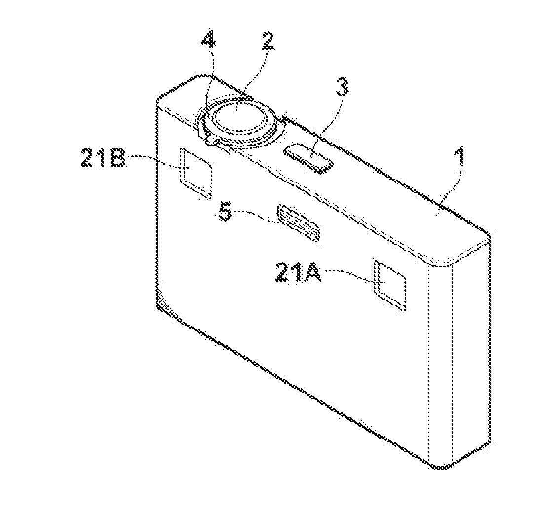
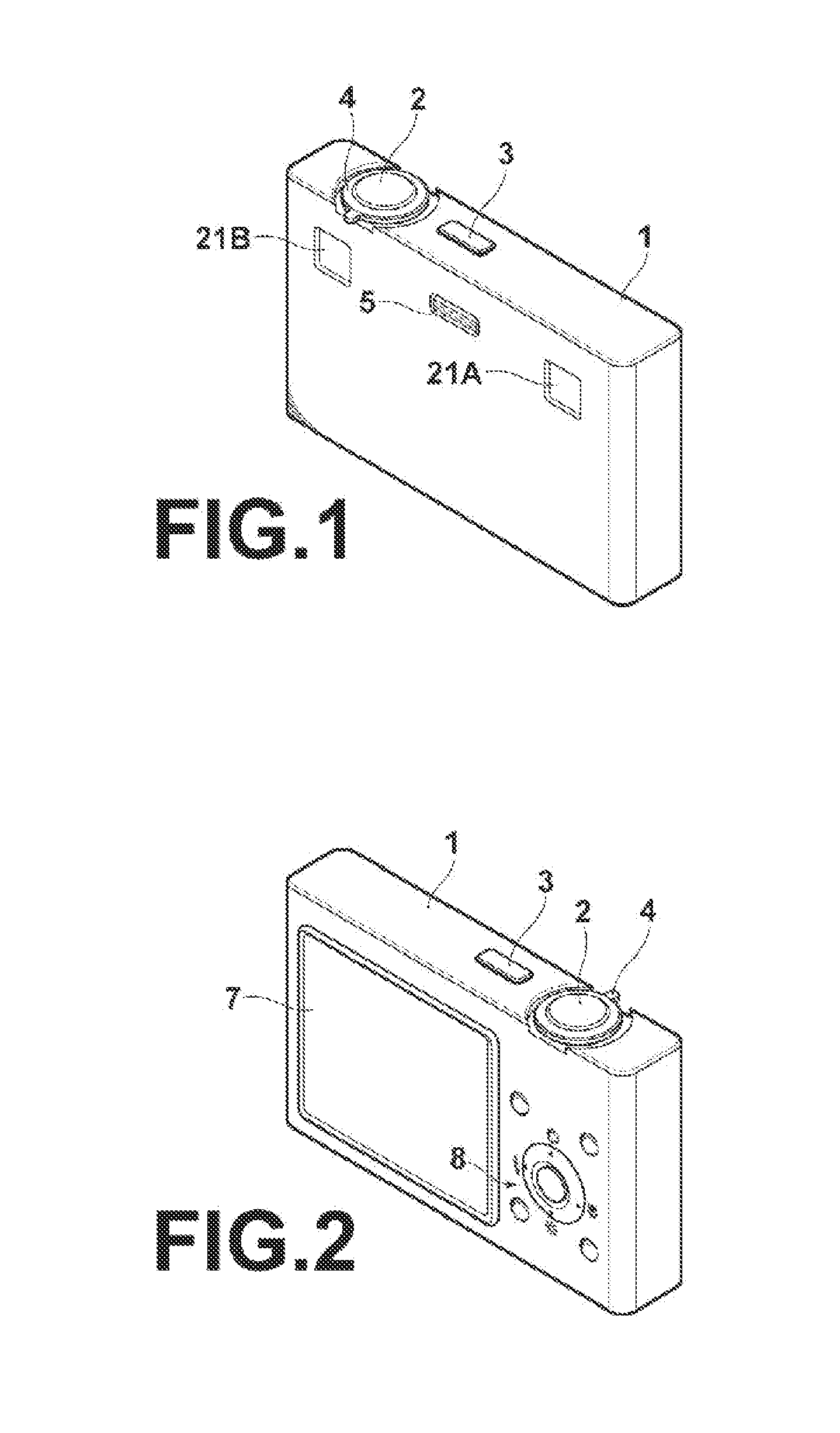
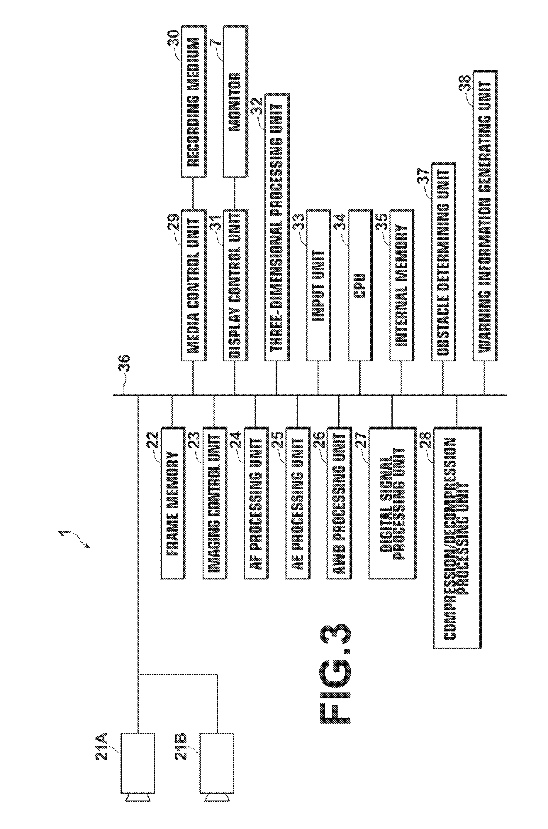
[0132]FIG. 15 is a flow chart illustrating the flow of a process carried out in the invention. First, when the half-pressed state of the release button 2 is detected (#1: YES), the preliminary images G1 and G2 for determining imaging conditions are obtained by the imaging units 21A and 21B, respectively (#2). Then, the AF processing unit 24, the AE processing unit 25 and the AWB processing unit 26 perform operations to determine various imaging conditions, and the components of the imaging units 21A and 21B are controlled according to the determined imaging conditions (#3). At this time, the AE processing unit 25 obtains the photometric values IV1 (i,j), IV2 (i,j) of the individual areas in the imaging ranges of the imaging units 21A and 213.

[0133]Then, at the obstacle determining unit 37, the index value obtaining unit 37A obtains the photometric values IV1 (i,j) IV2 (i,j) of the individual areas (#4), the area-by-area differential value calculating unit 37B calculates the differen...

second embodiment

[0150]As described above, in the invention, the mean index value calculating unit 37F combines the areas divided at the time of photometry, and calculates the mean photometric value of each combined area. Therefore, an error due to a parallax between the imaging units is diffused by combining the areas, thereby reducing erroneous determinations.

[0151]It should be noted that, in this embodiment, the index values (photometric values) of the combined areas are not limited to mean values of the index values of the areas before combined, and may be any other representative value, such as a median value.

[0152]In a third embodiment of the invention, among the areas IV1 (i,j), IV2 (i,j) at the time of photometry in the first embodiment, areas around the center are not counted.

[0153]Specifically, in step #7 of the flowchart shown in FIG. 15, the area counting unit 37D counts the number CNT of areas having absolute values |ΔIV (i,j)| of the differential values between the photometric values o...

third embodiment

[0156]the invention, as described above, uses a fact that an obstacle always enters the imaging range from the marginal areas thereof. By not counting the central areas, which are less likely to contain an obstacle, of each imaging range when the photometric values are obtained and the determination as to whether or not there is an obstacle is performed, the determination can be achieved with higher accuracy.

[0157]In a fourth embodiment of the invention, the AF evaluation values are used as the index values in place of the photometric values used in the first embodiment. Namely, operations in the fourth embodiment are the same as those in the first embodiment, except that, in step #4 of the flow chart shown in FIG. 15, the index value obtaining unit 37A in the block diagram shown in FIG. 11 obtains the AF evaluation values, which are obtained by the AF processing unit 24, of the individual areas in the imaging ranges of the imaging units 21A and 21B.

[0158]FIG. 22A shows one example ...


PUM


Abstract

An obstacle determining unit obtains predetermined index values for each of subranges of each imaging range of each imaging unit, compares the index values of the subranges at mutually corresponding positions in the imaging ranges of the different imaging units, and if a difference between the index values in the imaging ranges of the different imaging units is large enough to satisfy a predetermined criterion, determines that the imaging range of at least one of the imaging units contains an obstacle that is close to the imaging optical system of the at least one of the imaging units.

Description

BACKGROUND OF THE INVENTION[0001]1. Field of the Invention[0002]The present invention relates to a technique for determining whether or not there is an obstacle in an imaging range of imaging means during imaging for capturing parallax images for stereoscopically displaying a subject.[0003]2. Description of the Related Art[0004]Stereoscopic cameras having two or more imaging means used to achieve imaging for stereoscopic display, which uses two or more parallax images obtained by capturing the same subject from different viewpoints, have been proposed.[0005]With respect to such stereoscopic cameras, Japanese Unexamined Patent Publication No. 2010-114760 (hereinafter, Patent Document 1) pointed out a problem that, when stereoscopic display is performed using parallax images obtained from the individual imaging means of the stereoscopic camera, it is not easy to visually recognize such a situation that one of the imaging lenses is covered by a finger, since the portion covered by the ...

Claims


Application Information

Patent Timeline
Patent Type & Authority Applications(United States)
IPC IPC(8): H04N13/02H04N13/239
CPCG03B35/08H04N5/23293H04N13/0203H04N13/0239H04N5/2351H04N13/239H04N23/811H04N23/673H04N23/634H04N23/71H04N13/204
Inventor KOGUCHI, TAKEHIRO
Owner FUJIFILM CORP
Why Eureka
Try Eureka