Two Pi Solid Angle High Resolution Optical System

a solid angle, optical system technology, applied in the field of optical imaging systems, to achieve the effect of high resolution surveillan

Inactive Publication Date: 2013-05-09
STARK DANIEL LEE
View PDF2 Cites 9 Cited by
  • Summary
  • Abstract
  • Description
  • Claims
  • Application Information

AI Technical Summary

Benefits of technology

[0032]What is described is a unique, compact, high resolution, two pi steradians solid angle field of view optical design for use as a wide angle image collection system. At the curved image surface, multiple fiber plates translate the curved image surface to multiple flat image collection devices. The Fiber plates resolve a host of design issues as compared to current optical designs. The first issue, is translation of the image off of the curved surface to the flat image collection device surface allowing use of current image collection devices. The use of multiple image collection devices on a single optical system is unique. Another unique feature is use of the fiber plate's length to provide a radial translation away from the image surface into a larger volume, allowing placement of multiple image collection devices. The multiple fiber plates also resolve the fiber plate's numerical aperture issue by allowing the designer to select the maximum radiation input angle into the fi

Problems solved by technology

The first issue, is translation of the image off of the curved surface to the flat

Method used


Image

  • Two Pi Solid Angle High Resolution Optical System
  • Two Pi Solid Angle High Resolution Optical System
  • Two Pi Solid Angle High Resolution Optical System

Examples


Embodiment Construction

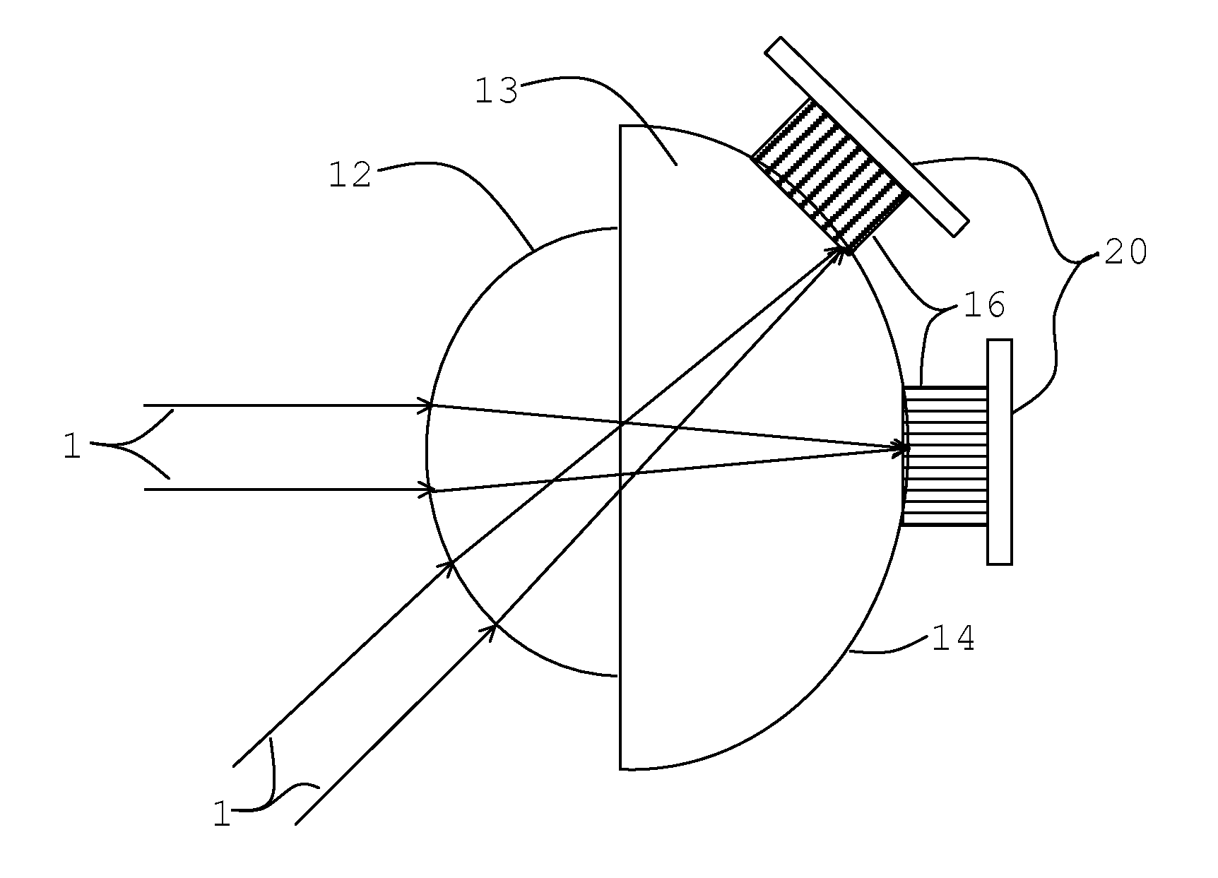
[0058]FIG. 5 Detailed Description

[0059]FIG. 5 is a side view showing two half ball lens, 12 and 13, with the spherical centers superimposed. The ball lenses are preferably optically fused at the center or fixed together with index of refraction adhesive. If an air gap is allowed between lenses 12 and 13, anti reflective coating is best applied to the surfaces. However, if not optically fused, the field of view is limited by the critical angle of reflection. The planer area outside of the center may be free or adhered with a compliant material to compensate for coefficient of thermal expansion. In the simplest design, ball lenses, 12 and 13, are the same index of refraction in order to avoid reflection and / or refraction at the interface between 12 and 13; however, different index of refractions complicate the design but also provide design advantages. An antireflective coating may be added if an air gap or dissimilar index of refractions are used for half ball lenses 12 and 13.

[0060]...


PUM


Abstract

This invention is a wide field surveillance optical system with inherent features being, non mechanical, compact, high resolution, a field of view up to two pi steradians solid angle. The optics design uses a single optical system and multiple flat image collection devices.
Multiple fiber plates translate the image off of the curved image surface to a plane for flat image collection devices. The fiber plates also act to translate the image into a larger volume as compared to the curved image surface, allowing required volume for the multiple image collection devices.
This invention uses a single optical system with multiple CCD or CMOS detectors. Advantages over prior art are simple optical designs, rugged optics because it can be manufactured as a single piece, and wider field of view without the sacrifice of resolution.

Description

CROSS REFERENCE TO RELATED APPLICATIONS[0001]noneSTATEMENT REGARDING FEDERALLY SPONSORED RESEARCH AND DEVELOPMENT[0002]All research and development associated with this invention has been performed using private funds. No federally sponsored research or development has been used.BACKGROUND OF THE INVENTION[0003]1. Field of Invention[0004]This invention discloses an optical imaging system design concept that supports close to a two pi steradians solid angle field of view or any subset solid angle thereof using one optical system with multiple flat image collection devices. The optical design maintains high resolution over the entire two pi steradians solid angle field of view and minimal spatial distortion.[0005]2. Description of Related Art[0006]There are many surveillance applications, for example, but not limited too: commercial surveillance, security situations, traffic control, robotics, and military applications. Desirable features are wide field of view, high resolution over t...

Claims


Application Information

Patent Timeline
IPC IPC(8): G02B13/06
CPCG02B13/06H04N7/18G03B37/06
Inventor STARK, DANIEL LEE
Owner STARK DANIEL LEE
Why Eureka
Try Eureka