Cartridge

Active Publication Date: 2013-05-09
CANON KK
View PDF1 Cites 56 Cited by
  • Summary
  • Abstract
  • Description
  • Claims
  • Application Information

AI Technical Summary

Benefits of technology

[0011]According to another aspect of the present invention, there is provided a cartridge detachably mountable to a main assembly of an image forming apparatus, comprising: a member to be supplied with electric energy; a frame molded with a resin material and provided with a through hole; and an electrode member formed on the frame by injection molding of an electroconductive resin material, and constituting a conducting path between the main assembly and the member to be supplied with electric energy when the cartridge is mounted to the main assembly, wherein the electrode member includes a penetrating portion

Problems solved by technology

Further, in the case where a plurality of electric contact portions were used, there was a need to determine their layout and connecting path in consideration of creepage distance and spatial distance between the electric contact portions and therefore there was a problem that the connecting path became complicated.
However, in such a case, the supporting member for the process means and the electroconductive resin material have no affinity and therefore adhesiveness therebetween is low, so that there is a possibility that it is difficult to ensure positional accuracy necessary for product function at the electric contact portion molded with the electroconduc

Method used


Image

  • Cartridge
  • Cartridge
  • Cartridge

Examples


Example

Embodiment 1

[0051]An electrophotographic image forming apparatus in this embodiment will be described. In the following description, of constituent members of the image forming apparatus, particularly, constitutions of the process cartridge, the developing cartridge and an electric contact portion (contact portion) and a molding method will be specifically described.

(Image Forming Apparatus)

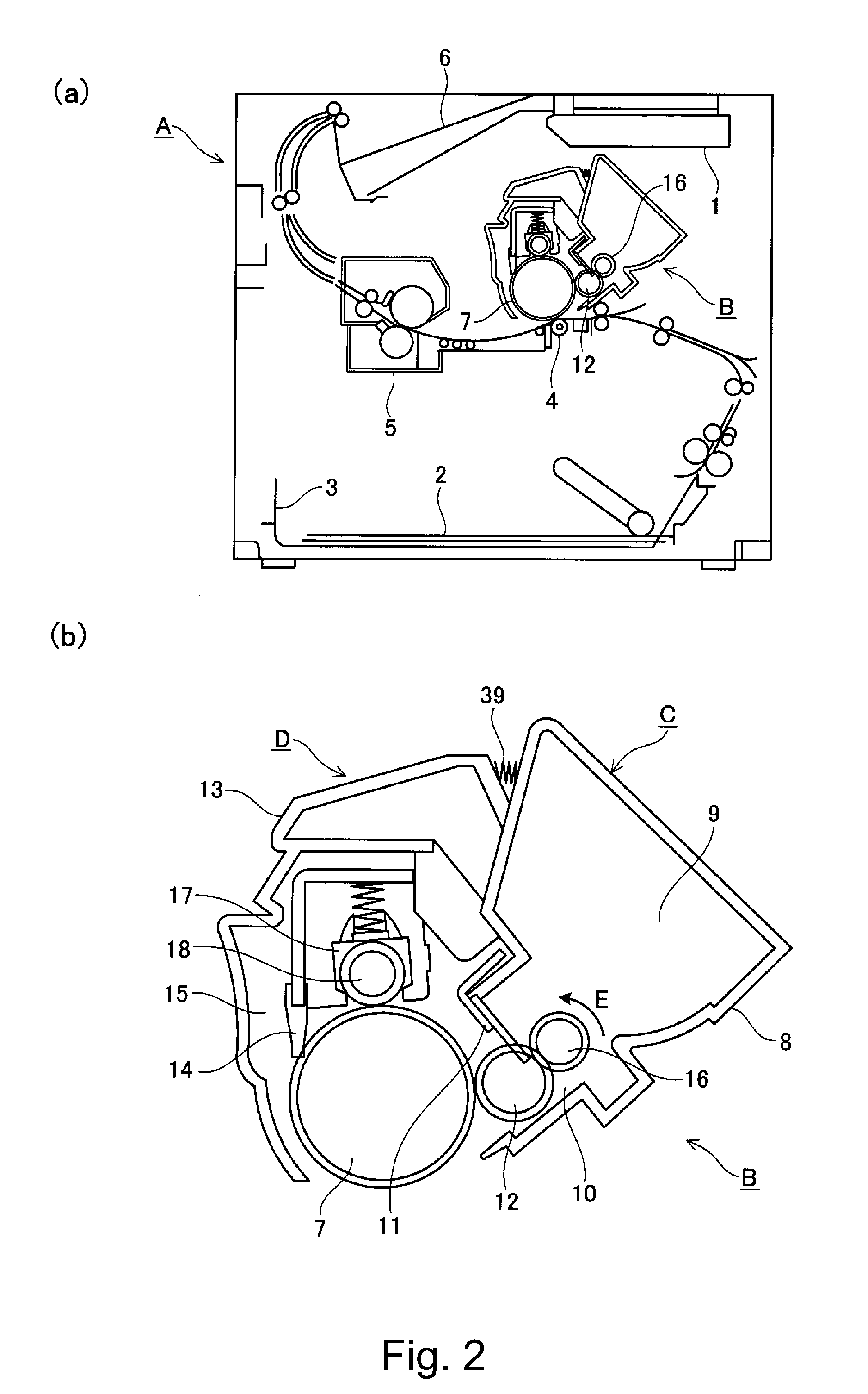
[0052]With reference to FIG. 2, an image forming apparatus A in this embodiment will be described.

[0053]Part (a) of FIG. 2 a schematic sectional view showing a structure of the image forming apparatus A (laser beam printer) in which a process cartridge B is mounted.

[0054]In the image forming apparatus A shown in (a) of FIG. 2, an image is formed on a recording material 2 in the following manner. First, an electrophotographic photosensitive drum 7 is irradiated with information light (laser light), on the basis of image information, emitted from an optical system 1, so that an electrostatic latent...

Example

Embodiment 2

[0142]A developing cartridge in Embodiment 1 will be described. The image forming apparatus in this embodiment is the same as that in Embodiment 1, thus being omitted from description. Similarly, the cross-sectional shape of the developing cartridge in this embodiment is the same as that in Embodiment 1 and therefore (b) of FIG. 12 is also referred to in this embodiment.

(Developing Cartridge)

[0143]A general structure of the developing cartridge will be described with reference to (b) of FIG. 2, (a) and (b) of FIG. 20 and (a) and (b) of FIG. 21.

[0144]Part (a) of FIG. 20 is a schematic perspective view showing a structure of the developing cartridge C in a state in which the process cartridge B is mounted in the main assembly of the image forming apparatus A, and (b) of FIG. 20 is a partial sectional view of the developing cartridge C shown in (a) of FIG. 20. Part (a) of FIG. 21 is a schematic side view showing a structure of a bearing member for the developing cartridge C...


PUM


Abstract

A cartridge detachably mountable to a main assembly of an image forming apparatus, includes: a member to be supplied with electric energy; a frame molded with a resin material; and an electrode member formed on the frame by injection molding of an electroconductive resin material. The electrode member includes a supporting portion for supporting the member to be supplied with electric energy and a contact portion to be contacted to a main assembly electric contact, provided in the main assembly, when the cartridge is mounted to the main assembly.

Description

FIELD OF THE INVENTION AND RELATED ART[0001]The present invention relates a cartridge detachably mountable to a main assembly of an image forming apparatus.[0002]Heretofore, in the image forming apparatus using an electrophotographic image forming process, a cartridge type in which a photosensitive drum and process means or a plurality of process means are integrally formed in a cartridge and the cartridge is detachably mountable to the image forming apparatus main assembly has been employed. In such a cartridge type, in a state in which the cartridge is mounted in the image forming apparatus main assembly, a main assembly electrode of the image forming apparatus main assembly and an electric contact portion of the cartridge are contacted, so that a member to be supplied with electric energy, such as the photosensitive drum or the process means is electrically connected to the image forming apparatus main assembly. As a result, it becomes possible to perform a process steps such as ...

Claims


Application Information

Patent Timeline
IPC IPC(8): G03G15/00
CPCG03G15/80G03G15/0896G03G2215/0872G03G21/1867G03G21/181
Inventor TAKARADA, HIROSHISUZUKI, AKIRAFUKUI, YUICHI
Owner CANON KK
Why Eureka
Try Eureka