Rotating type thin film deposition apparatus and thin film deposition method used by the same

a rotating type, thin film deposition technology, applied in vacuum evaporation coating, chemical/physical/physico-chemical processes, coatings, etc., can solve the problems of difficult to ensure uniform deposition, difficult to maintain uniform process conditions, continuous acceleration and deceleration period, etc., to achieve faster working speed and reduce the size of the thin film deposition apparatus

Active Publication Date: 2013-05-09
SAMSUNG DISPLAY CO LTD
View PDF47 Cites 12 Cited by
  • Summary
  • Abstract
  • Description
  • Claims
  • Application Information

AI Technical Summary

Benefits of technology

[0028]In the thin film deposition apparatus and method according to the present invention, since the deposition target is moved relative to the deposition device only at a constant speed while deposition is performed, thin layers can be precisely and uniformly formed on the entire surface of the deposition target, and since deposition is performed while a plurality of deposition targets move along a caterpillar track, a working speed is faster compared to a general reciprocating motion method, and the size of the thin film deposition apparatus can be reduced.

Problems solved by technology

However, when deposition is performed while the deposition target is moved relative to the deposition device in a reciprocating manner, an acceleration and deceleration period is continuously generated whenever the direction of movement of the deposition target is changed.
Thus, it is not easy to maintain uniform process conditions.
However, during an acceleration and deceleration period, the instants of time when the deposition target faces the deposition device are different in every period, and thus, it is difficult to ensure uniform deposition.
In addition, in a method whereby the deposition target is moved relative to the deposition device in a reciprocating manner, since deposition on the deposition target is completed and then deposition on the next deposition target can be performed, a working speed is very slow.
Thus, the size of the deposition device needs to be considerably large.

Method used


Image

  • Rotating type thin film deposition apparatus and thin film deposition method used by the same
  • Rotating type thin film deposition apparatus and thin film deposition method used by the same
  • Rotating type thin film deposition apparatus and thin film deposition method used by the same

Examples


Embodiment Construction

[0035]The present invention will now be described more fully with reference to the accompanying drawings, in which exemplary embodiments of the invention are shown.

[0036]First, a thin film deposition apparatus according to an embodiment of the present invention will be described.

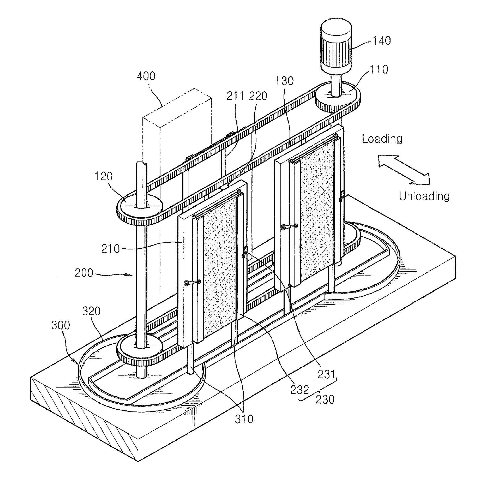
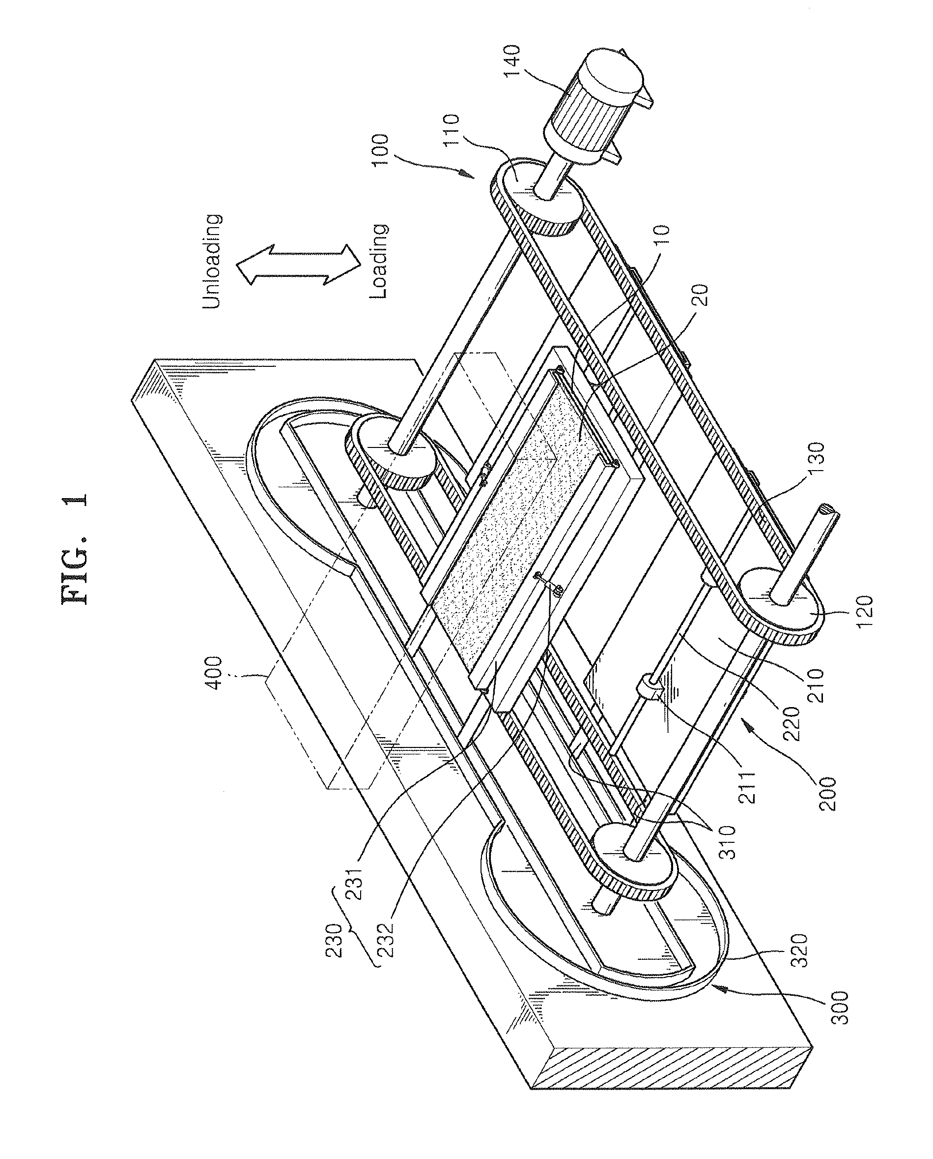
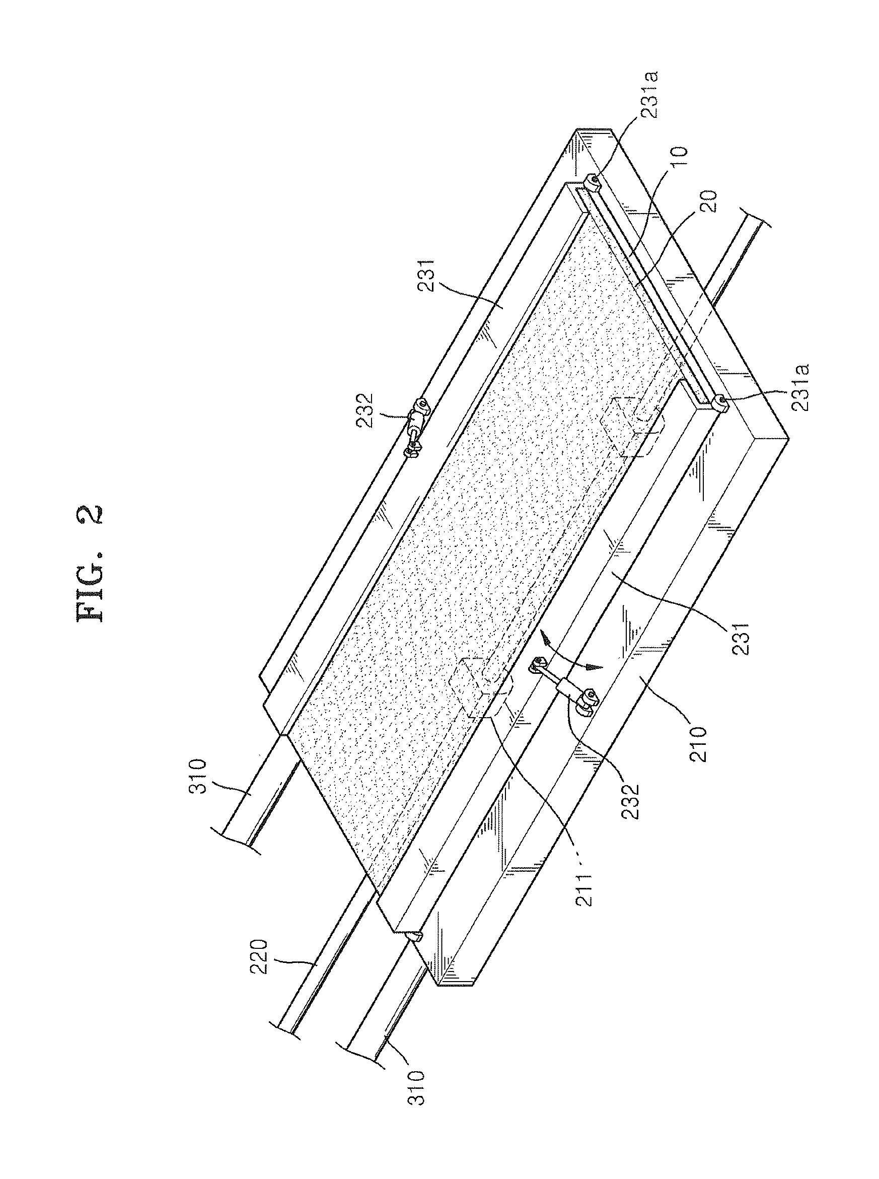
[0037]The thin film deposition apparatus illustrated in FIG. 1 includes a deposition device 400 that generates vapor in a deposition source, a circulation running unit 100 that runs on a circulation track via a deposition region (see D of FIG. 5) of the deposition device 400, and a support unit 200 that supports a substrate 10 as a deposition target together with a mask 20 and is moved along the circulation track. Thus, the substrate 10 is circulated on the circulation track along the circulation running unit 100 while being supported by the support unit 200, and deposition is performed by the deposition device 400 when the substrate 10 passes through the deposition region of the deposition device 400 on the...


PUM

PropertyMeasurementUnit
lengthaaaaaaaaaa
circumferential lengthsaaaaaaaaaa
speedaaaaaaaaaa

Abstract

A rotating type thin film deposition apparatus having an improved structure that allows continuous deposition, and a thin film deposition method used by the rotating type thin film deposition apparatus are provided. The rotating type thin film deposition apparatus includes a deposition device; a circulation running unit that runs a deposition target on a circulation track via a deposition region of the deposition device; and a support unit that supports the deposition target and moves along the circulation track. Thin layers can be precisely and uniformly formed on the entire surface of a deposition target, and since deposition is performed while a plurality of deposition targets move along a caterpillar track, a working speed is faster compared to a method involving a general reciprocating motion, and the size of the thin film deposition apparatus can be reduced.

Description

CLAIM OF PRIORITY[0001]This application makes reference to, incorporates the same herein, and claims all benefits accruing under 35 U.S.C. §119 from an application earlier filed in the Korean Intellectual Property Office on 3 Nov. 2011 and there duly assigned Serial No. 10-2011-0114126.BACKGROUND OF THE INVENTION[0002]1. Field of the Invention[0003]One or more embodiments of the present invention relate to a thin film deposition apparatus, in which vapor generated in a deposition source is deposited on the surface of a deposition target, and more particularly, to a rotating type thin film deposition apparatus having an improved structure that allows continuous deposition, and a thin film deposition method used by the rotating type thin film deposition apparatus.[0004]2. Description of the Related Art[0005]A deposition process whereby vapor generated in a deposition source is deposited on the surface of a deposition target, such as a substrate, is widely used in a thin film manufactu...

Claims


Application Information

Patent Timeline
Patent Type & Authority Applications(United States)
IPC IPC(8): C23C16/458
CPCC23C16/45551C23C16/458C23C14/50B01J19/1887B01J19/22C23C16/448C23C16/44H10K71/00
Inventor KIM, JIN-KWANGSEO, SANG-JOONKIM, SEUNG-HUN
Owner SAMSUNG DISPLAY CO LTD
Why Eureka
Try Eureka