Driver state detection system and method with accelerator pedal control function

Active Publication Date: 2013-05-09
HYUNDAI MOTOR CO LTD +1
View PDF4 Cites 6 Cited by
  • Summary
  • Abstract
  • Description
  • Claims
  • Application Information

AI Technical Summary

Benefits of technology

The driver state detection system and method with an accelerator pedal control system use an integrated accelerator pedal mechanism to improve fuel efficiency and prevent collisions. This system does not require a separate signal announcement structure, reducing production costs. Additionally, when the driver is carelessly driving the vehicle, a strong vibration signal is sent to alert the driver and improve stability. The driver state detection system and method also make sure the driver is aware of their actions and can react quickly to prevent accidents. This results in improved safety and performance of the vehicle.

Problems solved by technology

Accordingly, since the construction of the mechanism becomes complex, the production cost of the active accelerator pedal device may increase, and the durability thereof may decrease.

Method used


Image

  • Driver state detection system and method with accelerator pedal control function
  • Driver state detection system and method with accelerator pedal control function
  • Driver state detection system and method with accelerator pedal control function

Examples


Embodiment Construction

[0033]Reference will now be made in detail to various embodiments of the present invention(s), examples of which are illustrated in the accompanying drawings and described below. While the invention(s) will be described in conjunction with exemplary embodiments, it will be understood that present description is not intended to limit the invention(s) to those exemplary embodiments. On the contrary, the invention(s) is / are intended to cover not only the exemplary embodiments, but also various alternatives, modifications, equivalents and other embodiments, which may be included within the spirit and scope of the invention as defined by the appended claims.

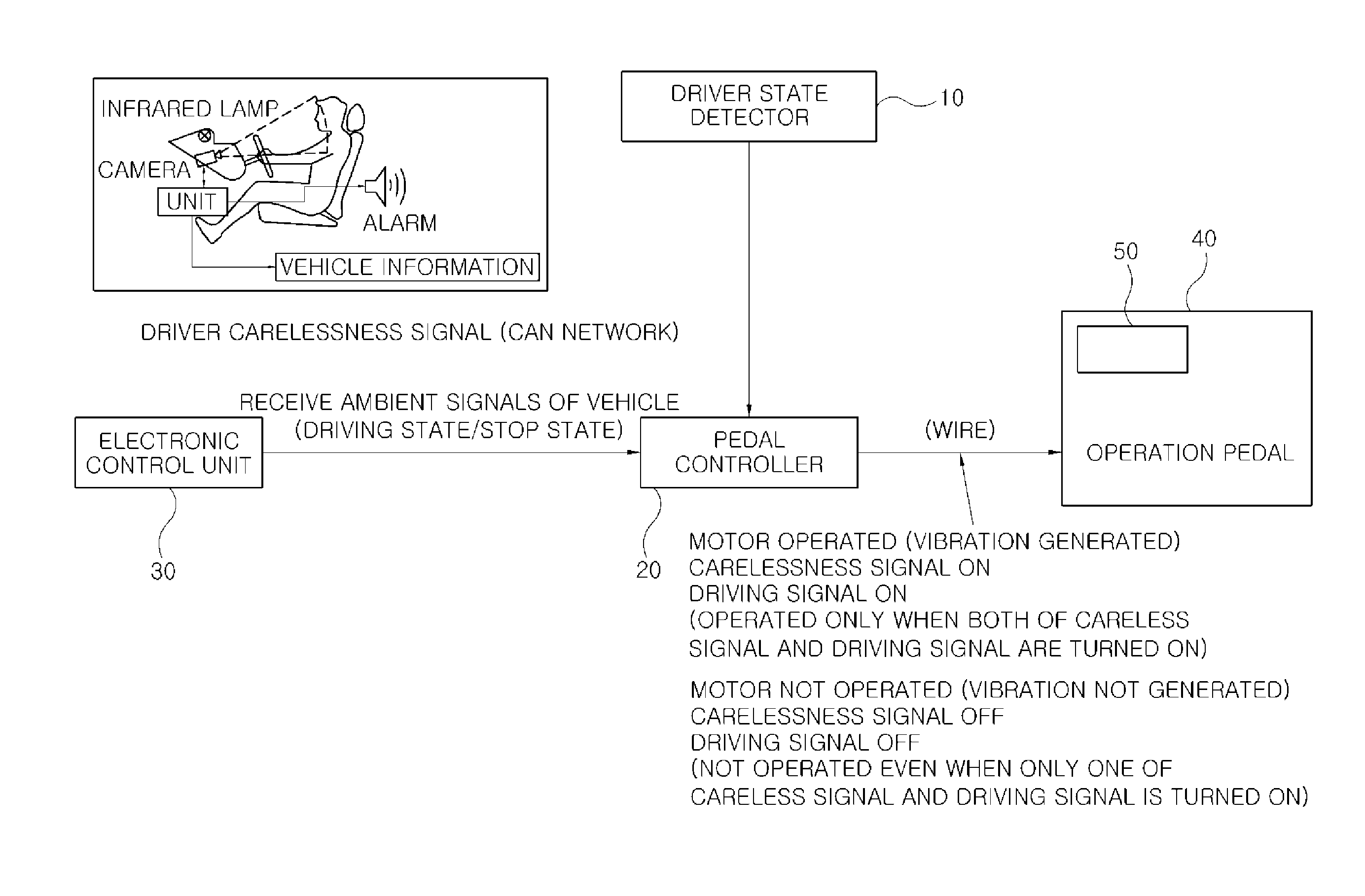
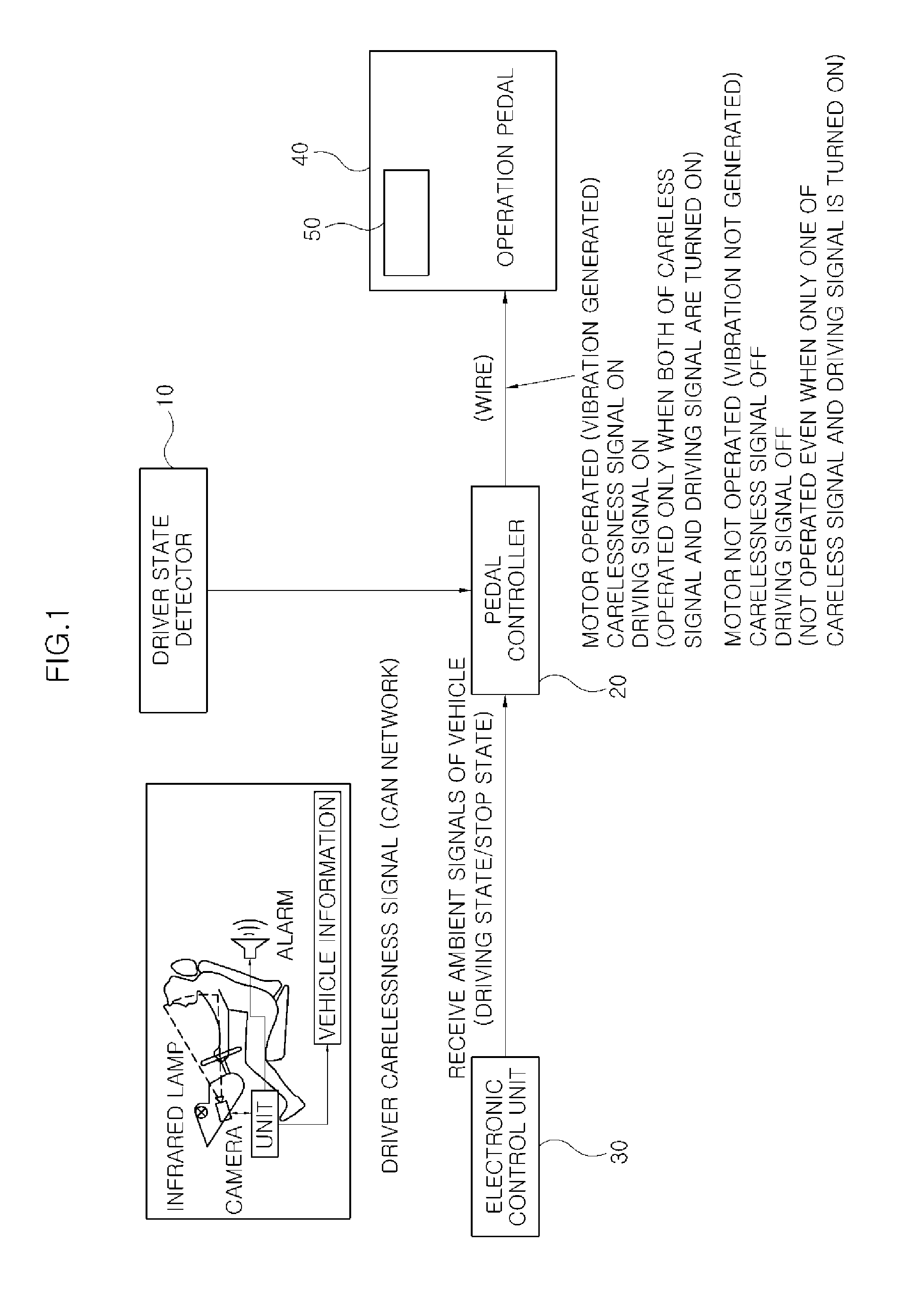
[0034]FIG. 1 schematically shows the configuration of a driver state detection system with an accelerator pedal control function according to various embodiments of the present invention. As illustrated in FIG. 1, the driver state detection system with an accelerator pedal control function according to various embodiments of the prese...


PUM


Abstract

A driver-state detection system and method with an accelerator pedal control function detects a driver's state and controlling an accelerator pedal to prevent an accident. The driver-state detection system with an accelerator pedal control function includes a driver-state detector detecting a driving state of a driver and determining whether the driver is carelessly driving a vehicle or not, a pedal controller receiving an operation signal from the driver-state detector, a vehicle state detector determining whether the vehicle is driven or stopped, based on ambient signals of the vehicle, an operation pedal installed to receive operation signals from the pedal controller and the vehicle state detector, and a vibration generator installed on the operation pedal and provided to generate or cancel a vibration of a motor.

Description

CROSS-REFERENCE TO RELATED APPLICATIONS[0001]The present application claims priority to Korean Patent Application Number 10-2011-0115865 filed Nov. 8, 2011, the entire contents of which application is incorporated herein for all purposes by this reference.BACKGROUND OF INVENTION[0002]1. Field of Invention[0003]The present invention relates to a driver state detection system and method with an accelerator pedal control function, and more particularly, to a driver state detection system and method with an accelerator pedal control function, which is capable of detecting a driver's state and controlling an accelerator pedal to prevent an accident.[0004]2. Description of Related Art[0005]In general, when a vehicle approaches a given extreme driving condition of a road, an active accelerator pedal device of the vehicle controls a pedal force of an accelerator pedal and informs the driver that the vehicle approached the extreme driving condition. When the driver drives the vehicle in a st...

Claims


Application Information

Patent Timeline
IPC IPC(8): G06F7/00
CPCB60W50/16B60K26/02B60K2026/022B60W2520/04B60W2540/30B60K28/066
Inventor KIM, EUNSIKCHO, YANGRAE
Owner HYUNDAI MOTOR CO LTD
Why Eureka
Try Eureka