Projected image planogram system

a projection image and planogram technology, applied in the field of retail displays, can solve the problems of time-consuming and costly display setting using traditional paper planograms, and the possibility of error in recreating the merchandise display in the store,

Active Publication Date: 2013-05-16
STEVNACY LLC
View PDF3 Cites 68 Cited by
  • Summary
  • Abstract
  • Description
  • Claims
  • Application Information

AI Technical Summary

Benefits of technology

[0034]In another feature and advantage of embodiments of the invention, the system accepts as an input a planogram image created outside of the PIPS system. The PIPS system uses image recognition algorithms to identify fixtures and merchandise within the image.
[0035]In another feature and advantage of embodiments of the invention, the information and images recorded are sent to other locations for recreation.
[0036]In another feature and advantage of embodiments of the invention, at the retail store or other environment where the planogram or design is to be set or recreated, a computer with projector attached displays on the pegboard or the display surface area. In embodiments, the display can include: an image of the completed planogram or design, illuminated shapes or images identifying fixture type, illuminated shapes or images identifying fixture locations, illuminated shapes or images identifying merchandise to be displayed, illuminated shapes or images identifying merchandise locations, and illuminated shapes or images identifying other items used or incorporated within the design. The illuminated shapes or images may incorporate the use of numerous colors, shapes, designs, textures, photographic images or other equivalents for delineation or identification.
[0037]In another feature and advantage of embodiments of the invention, illum

Problems solved by technology

Planogramming is one of the more costly payroll functions in retail.
Thus, display setting using traditional paper planograms is time-consuming and costly.
Further, the existing process used by retailers for setting planograms leaves much room for error in recreating the merchandise display in the store.
An error in the placement of one fixture when setting the plano

Method used


Image

  • Projected image planogram system
  • Projected image planogram system
  • Projected image planogram system

Examples


Embodiment Construction

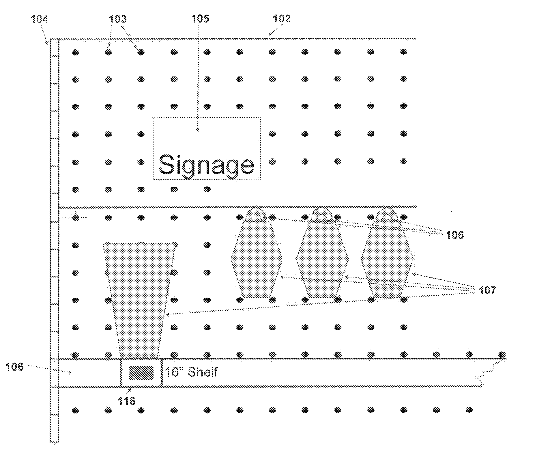
[0071]A more detailed description of the various embodiments of the present invention is provided with further references in the drawings beginning with FIG. 2A, a depiction of a store display pegboard section 102 with holes having the usual alignment of 1″ spacing both vertical and horizontal 103 with a metal stanchion 104. Store signage 105 for marketing is attached across the top of the display pegboard 102. Embodiments show fixtures 106 for displaying merchandise including a metal shelf 106 and peg hooks 106 with merchandise 107 displayed on the shelf 106 and hanging merchandise 107. FIG. 2B depicts the display framework base 108 and a digital camera 110 used to photograph the various aspects of the planogram as set in the corporate planogram room including the merchandise 107 hanging on the pegboard 102 via fixture hooks 106 inserted into pegboard holes 103. Camera 110 also records an image of the completed planogram as physically set in the corporate planogram room. Optionally...


PUM


Abstract

An automated projected image display planning and implementation system used in planogramming. Embodiments include a camera, projector, bar code reader, and software to store planograms as designed, communicate these planograms to retail locations, and provide an easy-to-use system insuring that the planograms are recreated as originally conceived. Embodiments create a unique QR code for storing and communicating fixture and merchandise data information as well as the relative placement location within the planogram. Embodiments are configured to project the image of the finished planogram on the display, and further, to illuminating the exact location within the planogram of merchandise and fixtures displayed on the planogram.

Description

TECHNICAL FIELD[0001]The invention relates generally to retail displays, and more particularly, to planograms used in displaying merchandise in a retail display.BACKGROUND[0002]The retail industry uses a process called planogramming for creating and communicating the design of a merchandise layout within a given category to be replicated at multiple retail locations. Typically created by corporate management or other centralized decision-makers, a planogram is an illustration, drawing, or instructions showing where products should be placed on pegboard or other display background surfaces. It also details what fixtures, shelves, hooks, or other product display holding equivalents are used for displaying these products.[0003]Retailers use planogramming to direct and influence consumers' purchases by creating merchandise displays that are well organized and visually appealing. The goal of planogramming is to increase sales and profits. Planogramming both improves the customer's shoppi...

Claims


Application Information

Patent Timeline
IPC IPC(8): G06Q10/08
CPCG06Q10/087
Inventor WINKEL, JAMES T.
Owner STEVNACY LLC
Why Eureka
Try Eureka