Multi-structure cathode for flexible organic light emitting diode (OLED) device and method of making same

a light-emitting diode and multi-structure technology, which is applied in the direction of organic semiconductor devices, solid-state devices, thermoelectric devices, etc., can solve the problems of device brightness decline, device internal heat generation, color shift and/or highly visible dark spots in the illumination field, etc., to achieve sufficient heat management without unduly inhibiting or limiting the flexibility of the device, and without unnecessarily restricting or inhibiting flexibility

Inactive Publication Date: 2013-05-16
AURONGZEB DEEDER MOHAMMAD
View PDF1 Cites 20 Cited by
  • Summary
  • Abstract
  • Description
  • Claims
  • Application Information

AI Technical Summary

Benefits of technology

[0008]For example, embodiments of the invention provide an OLED lighting device that is flexible or bendable, and which is capable of operating in high temperatures, e.g., above about 40 C. Since embodiments of such OLED devices are flexible, they may be mounted to any manner of curved support surface, such as a pole, curved wall or platform, a curved frame member, any type of non-flat fixture, and so forth. Accordingly, such flexible OLED lighting devices are significantly more versatile than rigid OLED lighting devices. Flexible OLED devices in accordance with embodiments of the present invention have a unique combination of characteristics that provide for heat management of the devices without unduly inhibiting or limiting flexibility of the devices. Characteristics of the OLED lighting devices are tailored to the intended bend configuration and active light area of the devices so as to provide sufficient heat management without unnecessarily limiting or inhibiting flexibility.

Problems solved by technology

OLED devices, which typically have an Al / Ag cathode structure and a thickness of less than 200 nm, are an efficient, high-brightness light source, but are not without certain inherent drawbacks.
The devices generate significant internal heat, which can be dissipated in larger area devices, but also operate in high temperature environments.
Prolonged exposure to high temperatures may induce localized degradation of the devices (e.g., de-lamination of the light-emitting layers), often resulting in color shift and / or highly visible dark spots in the illumination field.
High temperatures also result in an overall decrease in brightness of the device, thus limiting the useful life of the devices.
The premise of the '518 publication is that a cathode below 500 nm thickness will not provide sufficient heat conductivity, and that a “thick” cathode and thermally conductive cover are needed.
The flexible OLED devices are, however, subject to the same high temperature issues discussed above, in addition to the increased stresses in the light emitting materials resulting from bending or twisting the OLED devices.
The solution proposed by the '518 publication discussed above is not suitable for flexible OLED devices in that the increased thickness cathode and protective cover configuration only adds to the bending stresses and likely would induce cracking and delamination in the underlying layers.

Method used


Image

  • Multi-structure cathode for flexible organic light emitting diode (OLED) device and method of making same
  • Multi-structure cathode for flexible organic light emitting diode (OLED) device and method of making same
  • Multi-structure cathode for flexible organic light emitting diode (OLED) device and method of making same

Examples


Embodiment Construction

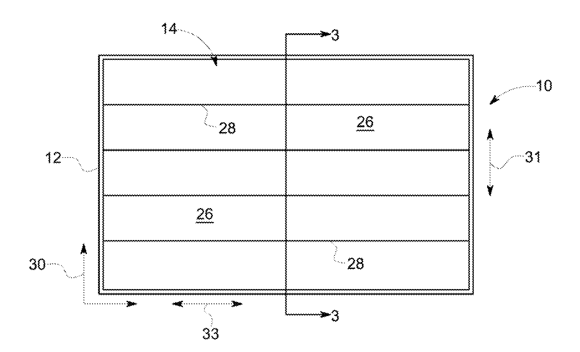
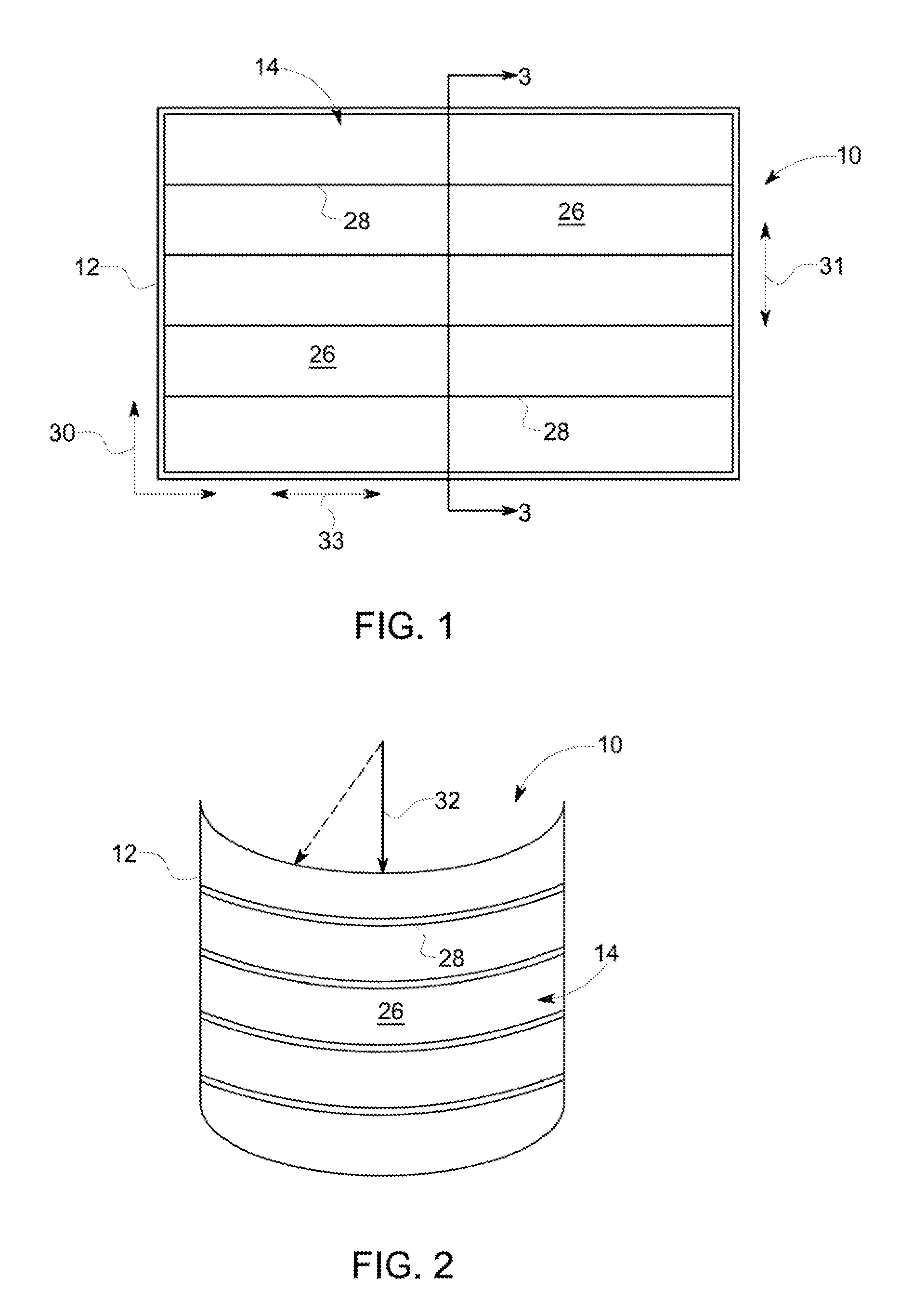
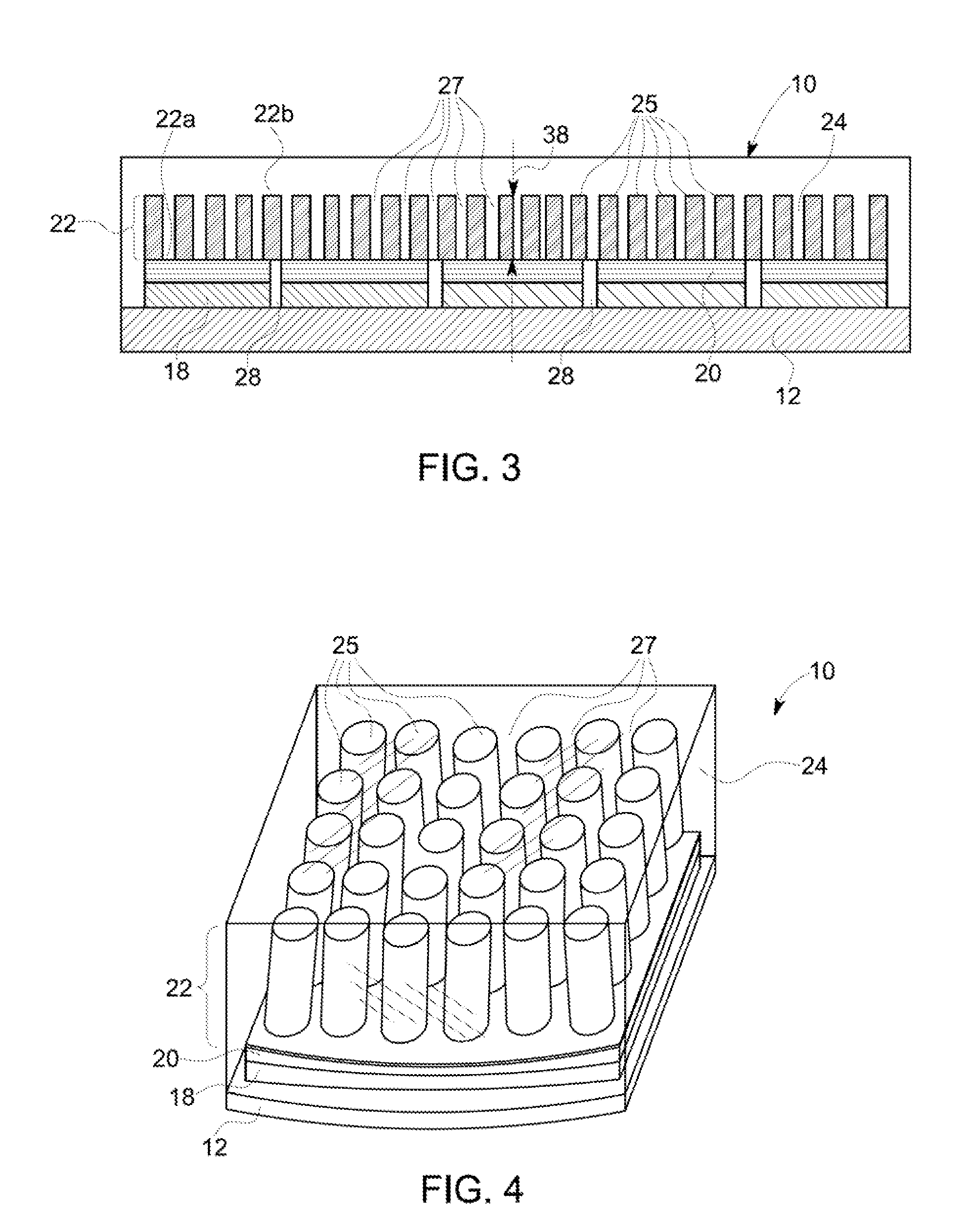
[0037]Reference now will be made in detail to embodiments of the invention, one or more examples of which are illustrated in the drawings. Each example is provided by way of explanation of the invention, not limitation of the invention. In fact, it will be apparent to those skilled in the art that various modifications and variations can be made in the present invention without departing from the scope or spirit of the invention. For instance, features illustrated or described as part of one embodiment can be used with another embodiment to yield a still further embodiment. Thus, it is intended that the present invention covers such modifications and variations as come within the scope of the appended claims and their equivalents. The same identifying numerals are used in the drawings to identify like elements throughout the Figures.

[0038]It is to be understood that the ranges and limits mentioned herein include all ranges located within the prescribed limits (i.e., sub-ranges and s...


PUM


Abstract

Described is a method for making a flexible OLED lighting device. The method includes forming a plurality of OLED elements on a flexible planar substrate, each of the OLED elements including a continuous respective anode layer formed over the substrate. One or more organic light emitting materials is formed over the anode layer; a continuous cathode layer having a first thickness is formed over the light emitting materials; and a discontinuous cathode layer having a second thickness is formed over the continuous cathode layer. An encapsulating protective cover may be formed over the cathode layers. Each of the OLED elements defines a bendable, continuous light region on the substrate, wherein the substrate and combination of OLED elements define an OLED device that more effectively dissipates heat and has an active light area that is bendable.

Description

FIELD OF THE INVENTION[0001]The field of the invention relates generally to organic light emitting diode (OLED) devices, and more particularly to a cathode structure in a flexible OLED device and method of making same.BACKGROUND OF THE INVENTION[0002]Organic electroluminescent devices, such as organic light emitting diodes (OLEDs), have been widely used for display applications, and the use of such devices in general lighting applications is gaining acceptance. An OLED device includes one or more organic light emitting layers disposed between two electrodes, e.g., a cathode and an anode, carried on a substrate. An encapsulating cover is disposed over the cathode. The OLED device may be “top-emitting”, wherein the produced light is emitted through the cover, or “bottom-emitting” wherein the produced light is emitted through the substrate. The organic light emitting layer emits light upon application of a voltage across the anode and cathode, whereby electrons are directly injected in...

Claims


Application Information

Patent Timeline
Patent Type & Authority Applications(United States)
IPC IPC(8): H01L51/52H01L51/56
CPCH01L51/0097H01L51/5225Y02E10/549H01L2251/558H01L51/5253H10K77/111H10K50/822H10K50/844H10K2102/351
Inventor AURONGZEB, DEEDER MOHAMMAD
Owner AURONGZEB DEEDER MOHAMMAD
Why Eureka
Try Eureka