
Computing device and method for calibrating star probe of image measuring machine

a technology of image measuring machine and computer device, which is applied in the field of computer device, storage medium, and method for calibrating star probe of image measuring machine, can solve the problem of movable arm precision length

Inactive Publication Date: 2013-05-16
HONG FU JIN PRECISION IND (SHENZHEN) CO LTD +1
View PDF0 Cites 12 Cited by
  • Summary
  • Abstract
  • Description
  • Claims
  • Application Information

AI Technical Summary

Benefits of technology

The patent is about a system and method for calibrating a probe of an image measuring machine. It uses a computing device and a storage medium to improve the accuracy of the probe. The technical effect is to make the image measuring machine more precise and reliable.

Problems solved by technology

However, the star probe calibration process may result in acceptable calibration results as the precision length of the movable arm is difficult and costly to produce, and is also time consuming as the image measuring machine would need to be manually manipulated between various measuring positions of the workpiece with respect to the star probe.

Method used


Image

  • Computing device and method for calibrating star probe of image measuring machine
  • Computing device and method for calibrating star probe of image measuring machine
  • Computing device and method for calibrating star probe of image measuring machine

Examples


Embodiment Construction

[0010]The present disclosure, including the accompanying drawings, is illustrated by way of examples and not by way of limitation. It should be noted that references to “an” or “one” embodiment in this disclosure are not necessarily to the same embodiment, and such references mean “at least one.”

[0011]In the present disclosure, the word “module,” as used herein, refers to logic embodied in hardware or firmware, or to a collection of software instructions, written in a program language. In one embodiment, the program language may be Java, C, or assembly. One or more software instructions in the modules may be embedded in firmware, such as in an EPROM. The modules described herein may be implemented as either software and / or hardware modules and may be stored in any type of non-transitory computer-readable medium or other storage device. Some non-limiting examples of a non-transitory computer-readable medium include CDs, DVDs, flash memory, and hard disk drives.

[0012]FIG. 1 is a block...


PUM


Abstract

In a method for calibrating a star probe of an image measuring machine, the star probe includes one or more probe heads. Probe configuration information for the star probe is configured when there is no probe configuration file of the star probe stored in a storage device of the image measuring machine, and one of the probe heads to be calibrated is selected from the star probe. The method calibrates a radius value of the selected probe head, and calibrates the deviation between the center point of the selected probe head and the focus of the camera lens. The method further generates a star probe model of the star probe according to the probe configuration information and the probe calibration information, and displays the star probe model of the star probe on a display device of the image measuring machine.

Description

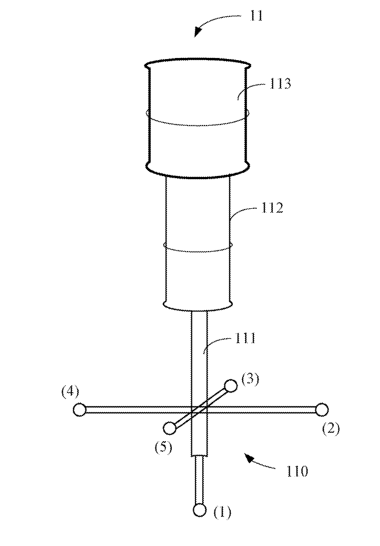
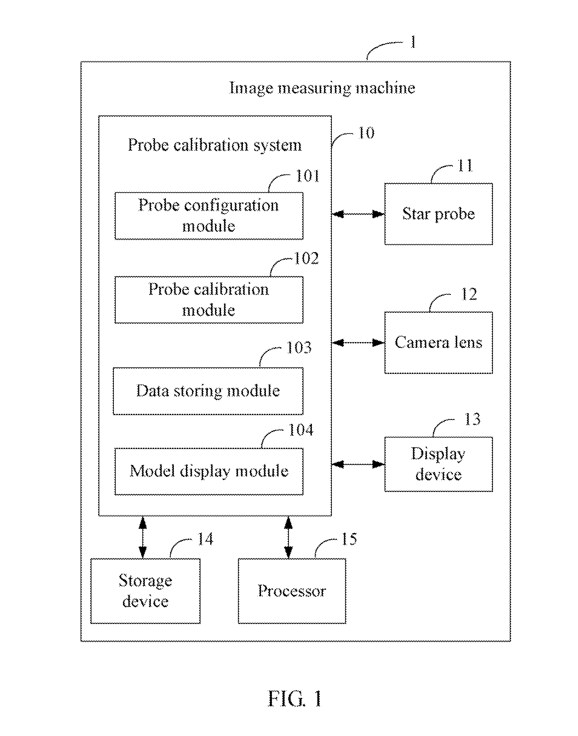
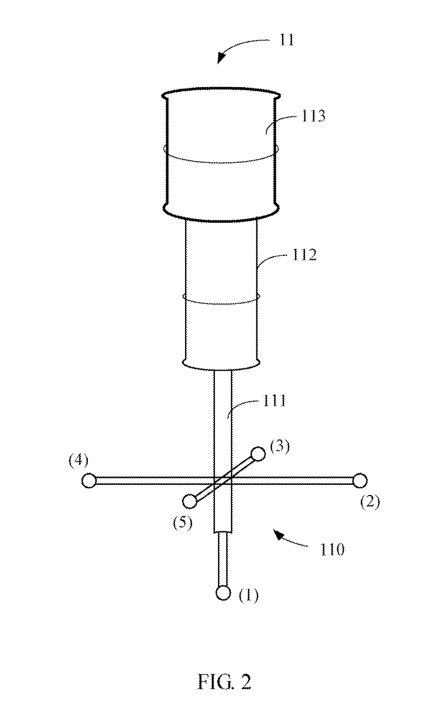
BACKGROUND[0001]1. Technical Field[0002]Embodiments of the present disclosure relate to probe measurement systems and methods, and particularly to a computing device, a storage medium, and a method for calibrating a star probe of an image measuring machine.[0003]2. Description of Related Art[0004]Coordinate measurement machines, such as image measuring machines, can be used to perform a variety of measurement and coordinate acquisition tasks. In an image measuring machine, a movable arm having one or more transfer members can be connected to a star probe for measuring various dimensions of workpieces. To obtain optimal precision and accuracy of the measurements, the star probe must initially be calibrated before it can be used in the image measuring machine. However, the star probe calibration process may result in acceptable calibration results as the precision length of the movable arm is difficult and costly to produce, and is also time consuming as the image measuring machine wo...

Claims


Application Information

Patent Timeline
Patent Type & Authority Applications(United States)
IPC IPC(8): H04N7/18
CPCG01B11/03G01B11/00
Inventor CHANG, CHIH-KUANGSHE, ZHENG-CAIYUAN, ZHONG-KUIZOU, ZHI-JUNLI, DONG-HAI
Owner HONG FU JIN PRECISION IND (SHENZHEN) CO LTD
Learn More