Water filling system for reactor water level gauge

a technology of water level gauge and water filling system, which is applied in the direction of nuclear engineering, greenhouse gas reduction, nuclear elements, etc., can solve the problems of difficult filling of instrumentation pipes, malfunction or instruction error of measuring gauges,

Active Publication Date: 2013-05-16
KK TOSHIBA
View PDF18 Cites 6 Cited by
  • Summary
  • Abstract
  • Description
  • Claims
  • Application Information

AI Technical Summary

Benefits of technology

[0015]According to the embodiment of the present invention of the characters mentioned above, The present invention can provide a water filling system for a reactor water level gauge capable of filling the reactor water level gauge instrumen

Problems solved by technology

However, due to an earthquake, in the reactor water level gauge 1, water in the instrumentation pipe 1a in a reactor containment vessel 6 evaporates to cause a malfunction or an instruction error of measuring gauges.
Further, the reactor building 5 housing gauges is brou

Method used


Image

  • Water filling system for reactor water level gauge
  • Water filling system for reactor water level gauge
  • Water filling system for reactor water level gauge

Examples


first embodiment

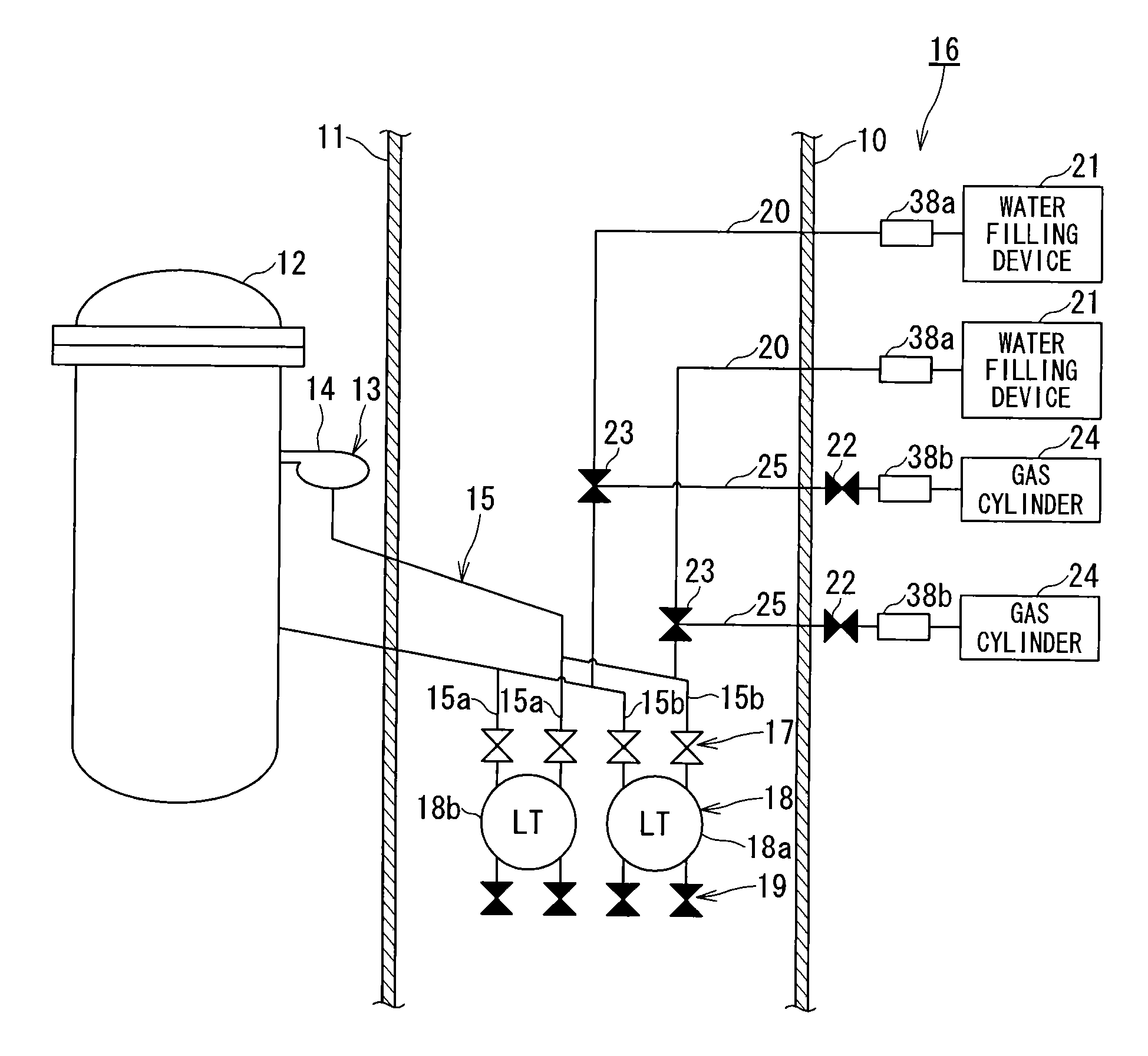
[0029]FIG. 1 is a configuration diagram of a water filling system for a reactor water level gauge according to a first embodiment.

[0030]In a nuclear power plant, a reactor containment vessel 11 is provided in a reactor building 10, and houses a reactor pressure vessel 12. In the reactor building 10, a reactor water level gauge 13 that measures a water level in the reactor pressure vessel 12 is provided. The reactor water level gauge 13 includes a reactor water level gauge instrumentation pipes 15 in the reactor building, connected to two vertically upper and lower portions of the reactor pressure vessel 12. The two reactor water level gauge instrumentation pipes 15 in the reactor building are extended into the reactor building 10 through unshown penetration in the reactor containment vessel 11. Among two vertical connecting portions of the reactor pressure vessel 12, a condensation bath 14 can be provided on the upper connecting portion, and a plurality of, for example, four condens...

first modification

of First Embodiment

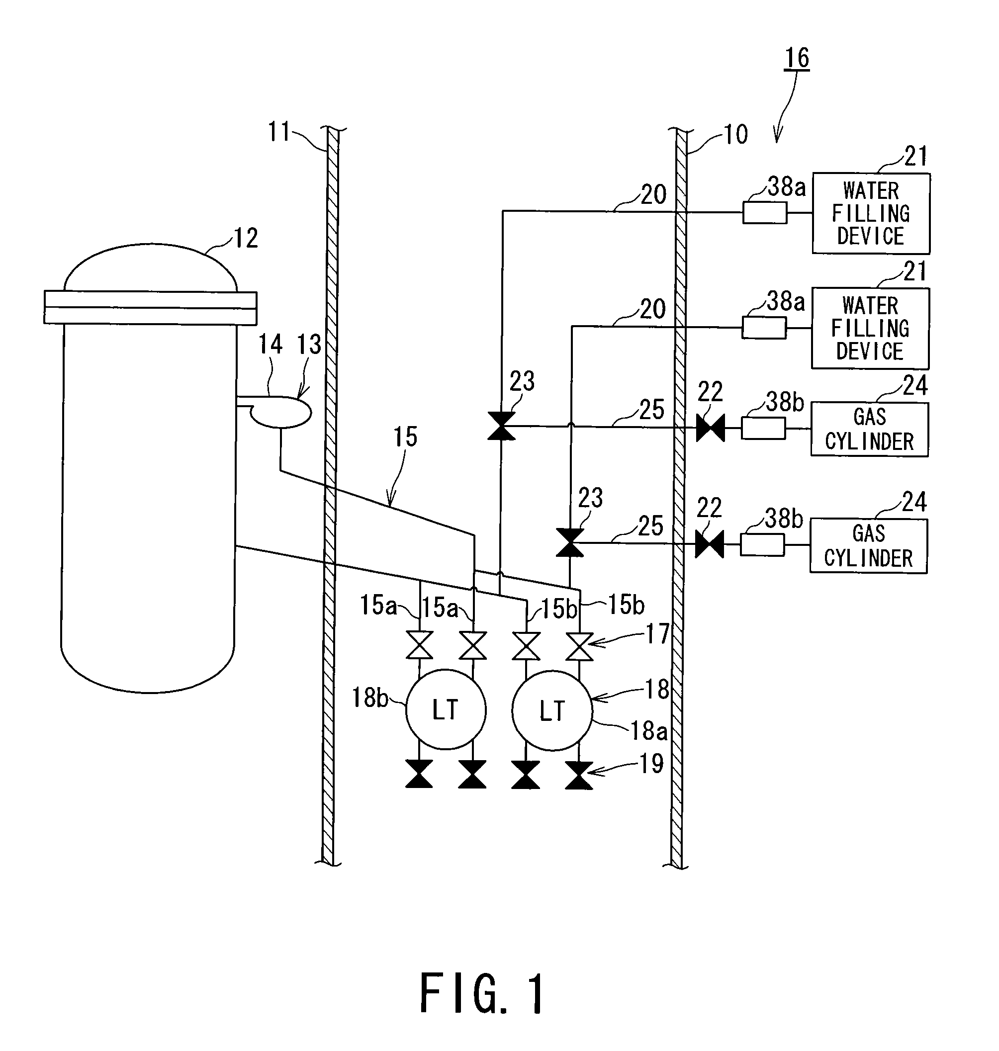
[0038]FIG. 2 shows a first modification (modified embodiment) of the first embodiment.

[0039]The first modification is such that a CRD pump (control rod drive mechanism) 40 is used to supply water to the reactor water level gauge instrumentation pipe 15 in the reactor building in the first embodiment of the water filling system 16 for a reactor water level gauge. As shown in FIG. 2, during operation of the plant, the CRD pump 40 supplies water to a CRD 39, and the CRD 39 supplies water to the reactor water level gauge instrumentation pipe 15. Since it cannot be expected that the CRD pump 40 operates at a time of an accident, if the reactor water level gauge instrumentation pipe 15 needs to be filled with water at the time of an accident, the water filling system 16 for the reactor water level gauge 13 uses the water filling instrumentation pipe 20 from the water filling device 21. Thus, the gas cylinder 24 is connected to open the separation valve 23, and the water...

second modification

of First Embodiment

[0040]FIG. 3 shows a second modification (modified embodiment) of the first embodiment of the water filling system for a reactor water level gauge.

[0041]The second modification has a structure in which the gauge test valve 19 is replaced by a separation valve 23. The separation valve 23 is provided below the transmitter 18a instead of the gauge test valve 19. The water filling instrumentation pipe 20 is extended from the separation valve 23 to an outside of the reactor building 10, and the water filling device 21 can be connected via a joint 38a outside the reactor building 10. Further, the separation valve 23 can be operated from outside the reactor building 10 by the water filling instrumentation pipe 20 and the gas cylinder 24. The water filling procedure is the same as in FIG. 1, and thus, detail will be omitted herein. This case has characteristic feature such that the number of gauge test valves 19 is smaller than in the first embodiment.


PUM


Abstract

A water filling system for a reactor water level gauge is provided for filling a reactor water level gauge instrumentation pipe in a reactor building with water and filling the reactor water level gauge with water even in an unexpected abnormal event where the reactor building is brought into a highly radioactive environment. The water filling system for a reactor water level gauge includes a water filling instrumentation pipe guided from the reactor water level gauge instrumentation pipe in the reactor building to an outside of the reactor building and filling the reactor water level gauge instrumentation pipe in the reactor building with water even in an unexpected abnormal event of a nuclear power plant.

Description

BACKGROUND OF THE INVENTION[0001]1. Field of the Invention[0002]The present invention relates to a water filling technique capable of filling a reactor water level gauge with water even in an unexpected abnormal event where a reactor building is brought into a highly radioactive environment.[0003]2. Description of the Related Art[0004]In a nuclear power plant, a reactor holds water, and hydraulic head pressure of water is measured to measure a reactor water level. An instrumentation pipe of a reactor water level gauge that measures a reactor water level is filled with water.[0005]As shown in FIG. 11, such instrumentation pipe 1a of a reactor water level gauge 1 is connected via a gauge test valve 2 to a pump 3. The gauge test valve 2 is opened, and the pump 3 is used to fill the instrumentation pipe 1a of the reactor water level gauge 1 with water from a makeup water system (MUW) or water in a tank 4 left overnight in terms of preventing inflow of air.[0006]In a reactor building 5, ...

Claims


Application Information

Patent Timeline
IPC IPC(8): G21C17/00
CPCG21C17/00G21C15/182Y02E30/40G21C17/035G21C17/02Y02E30/30
Inventor SHIRAISHI, FUJIOFUKAI, HISAYOSHI
Owner KK TOSHIBA
Why Eureka
Try Eureka