Method of Determining Spatial Response Signature of Detector in Computed Radiography

a detector and computed radiography technology, applied in the direction of material analysis using wave/particle radiation, instruments, applications, etc., can solve the problems of imposing tough requirements, excessive detector sensitivity variability, and easy generation of costly yield loss in detector manufacturing, etc., to achieve the effect of reducing the cost of detector manufacturing, and reducing the accuracy of detection

Active Publication Date: 2013-05-16
AGFA NV
View PDF6 Cites 5 Cited by
  • Summary
  • Abstract
  • Description
  • Claims
  • Application Information

AI Technical Summary

Benefits of technology

[0005]Mammography, an image quality wise highly demanding CR market, imposes tough requirements to the magnitude and spatial extent of the detector's sensitivity variability distribution. Stringent IPS control is key to preserve a sufficient visibility of tiny objects like micro-calcifications and the sharp delineation of subtle, medium to large structures inside the breast tis

Problems solved by technology

Mammography, an image quality wise highly demanding CR market, imposes tough requirements to the magnitude and spatial extent of the detector's sensitivity variability distribution.
Image plate artifacts, isolated sensitivity disturbances, also part of a detector's characterist

Method used


Image

  • Method of Determining Spatial Response Signature of Detector in Computed Radiography
  • Method of Determining Spatial Response Signature of Detector in Computed Radiography
  • Method of Determining Spatial Response Signature of Detector in Computed Radiography

Examples


Embodiment Construction

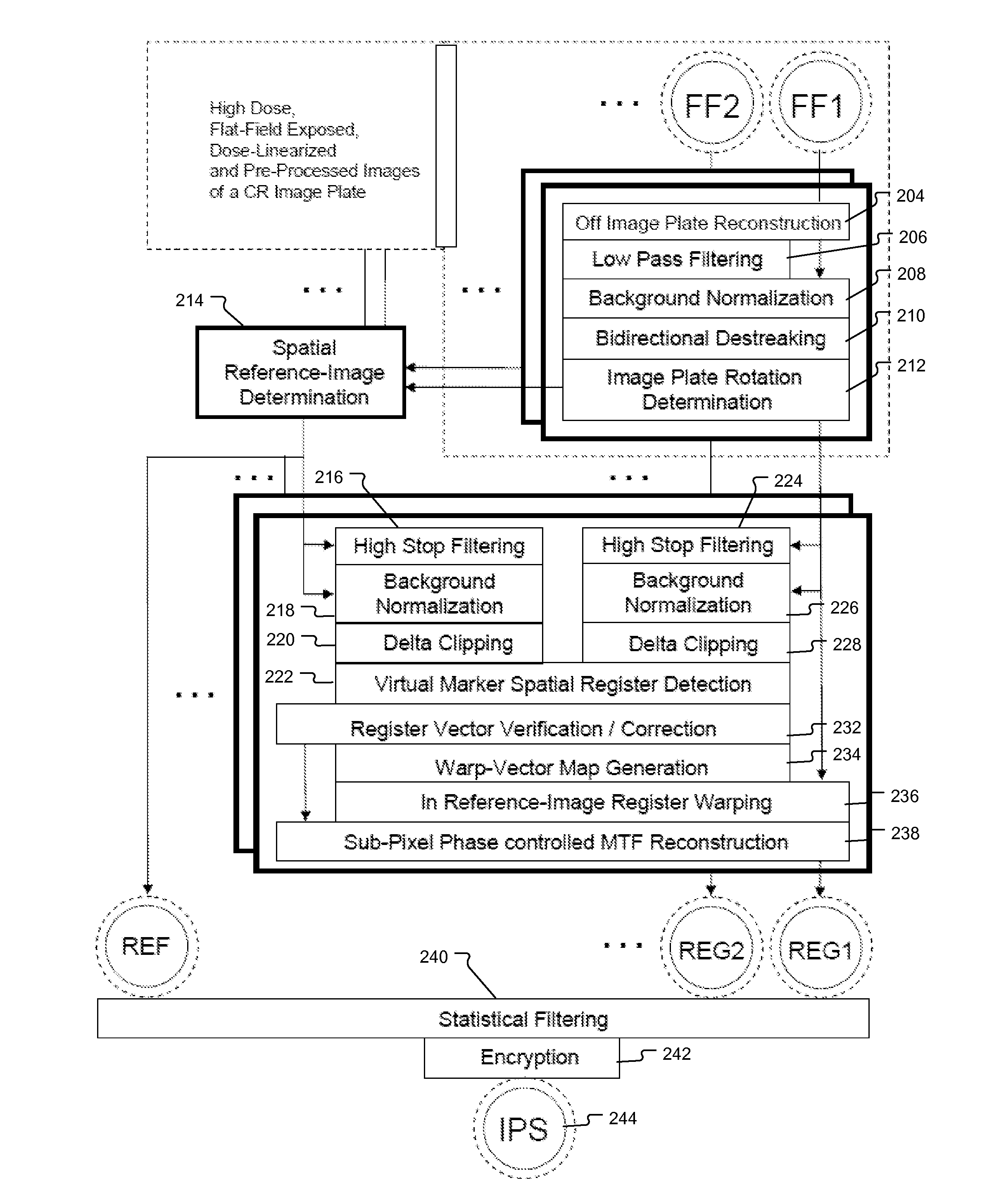
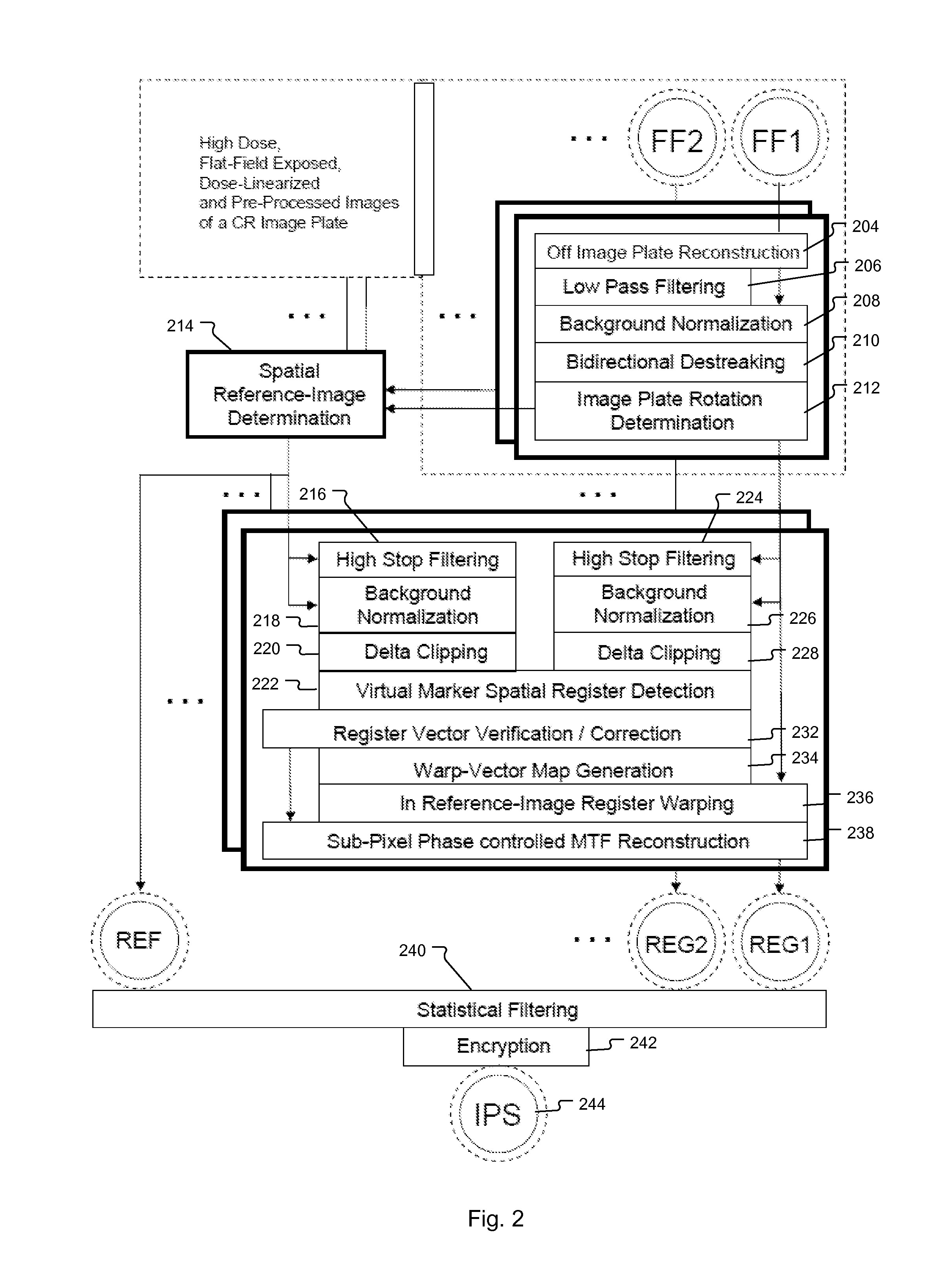
[0021]Below a specific embodiment of the process of determining an image plate's (also called ‘CR detector’) spatial response signature is described.

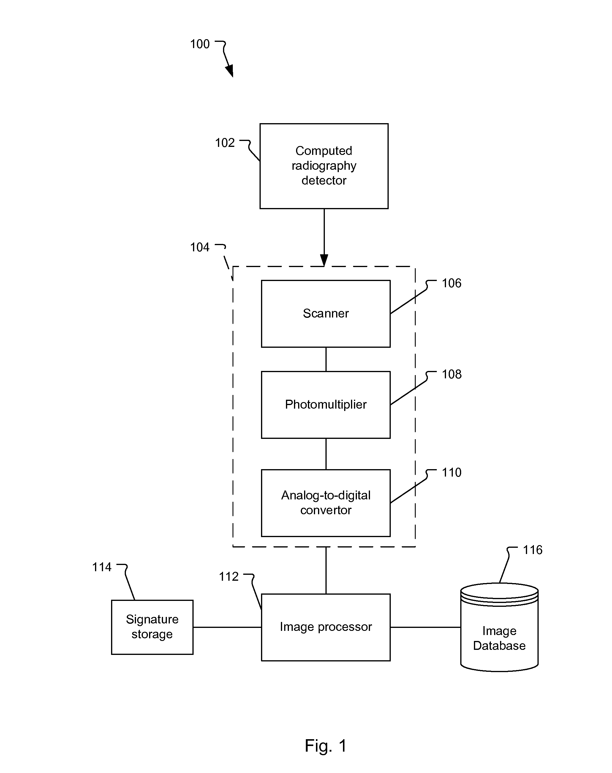
[0022]The image plate 102 used in computed radiography typically comprises a photo-stimulable phosphor.

[0023]Examples of suitable detectors 102 comprising a photo-stimulable phosphor are described e.g. in European patent application 1 818 943 and European patent application 1 526 552.

[0024]Flat Field Image Generation

[0025]The process in its most general formulation comprises the steps of generating a flat field image by homogeneously exposing a well-cleaned detector 102 to radiation such as X-rays and scanning, preferably line-wise scanning, the homogeneously exposed detector by means of light, e.g. laser light and by digitizing the scanned image.

[0026]Next, a low-pass filtered version of the flat field image is generated and the flat field image is background demodulated by means of corresponding pixel values in said low-pass filtered ...


PUM


Abstract

Method and system for determining the spatial response signature of a x-ray detector comprising a photostimulable phosphor by generating a flat field image of the detector, generating a low-pass filtered version of the flat field image and background demodulating the flat field image by pixel-wise dividing it by means of corresponding pixel values in the low-pass filtered version.

Description

RELATED APPLICATIONS[0001]This application is a Continuation of International Application No. PCT / EP2011 / 060677, filed on Jun. 27, 2011, now International Publication No. WO 2012 / 007264, published on Jan. 19, 2012, which International Application claims priority to European Patent Application No. 10169607.8, filed on Jul. 15, 2010, now European Patent Publication No. 2 407 106, published on Jan. 18, 2012, and claims the benefit under 35 U.S.C. 119(e) of U.S. Provisional Application No. 61 / 364,648, filed on Jul. 15, 2010, all of which are incorporated herein by reference in their entirety.BACKGROUND OF THE INVENTION[0002]Computed radiography (CR) performance is tightly coupled to the overall image quality and detection capabilities of the entire image acquisition, processing and display chain. For diagnosis or during technical image quality testing patient—or target (phantom)—images are created on an intermediate storage medium, called image plate or detector. During exposure the ima...

Claims


Application Information

Patent Timeline
IPC IPC(8): G01N23/00
CPCA61B6/4216G01N23/00A61B6/585A61B6/583
Inventor CRESENS, MARCVAN GOUBERGEN, HERMAN
Owner AGFA NV
Why Eureka
Try Eureka