Inspection of region of interest

a technology of imaging and region, applied in image analysis, image enhancement, instruments, etc., can solve the problems of difficult to perceive subtle anomalies and irregularities in such imagery, inability to control conditions, and limited diagnostic performance in endoscopy, radiology, and ultrasound applications

Inactive Publication Date: 2013-05-16
D V P TECH
View PDF10 Cites 58 Cited by
  • Summary
  • Abstract
  • Description
  • Claims
  • Application Information

AI Technical Summary

Problems solved by technology

When imaging cluttered scenes in varying conditions (noise, clutter, dynamic range, dynamic motion), it is often difficult to perceive subtle anomalies and irregularities in such imagery.
This is especially true in imaging situations where such conditions cannot be controlled in terms of signal to background, signal to noise and signal to clutter.
For example, the diagnostic performance in endoscopy, radiology, and ultrasound applications is often limited by low signal to noise levels.
Such indications may be in the superficial layers of tissue, as well as in deeper layers of tissue, which make them more difficult to visualize and detect.

Method used


Image

  • Inspection of region of interest
  • Inspection of region of interest
  • Inspection of region of interest

Examples


Embodiment Construction

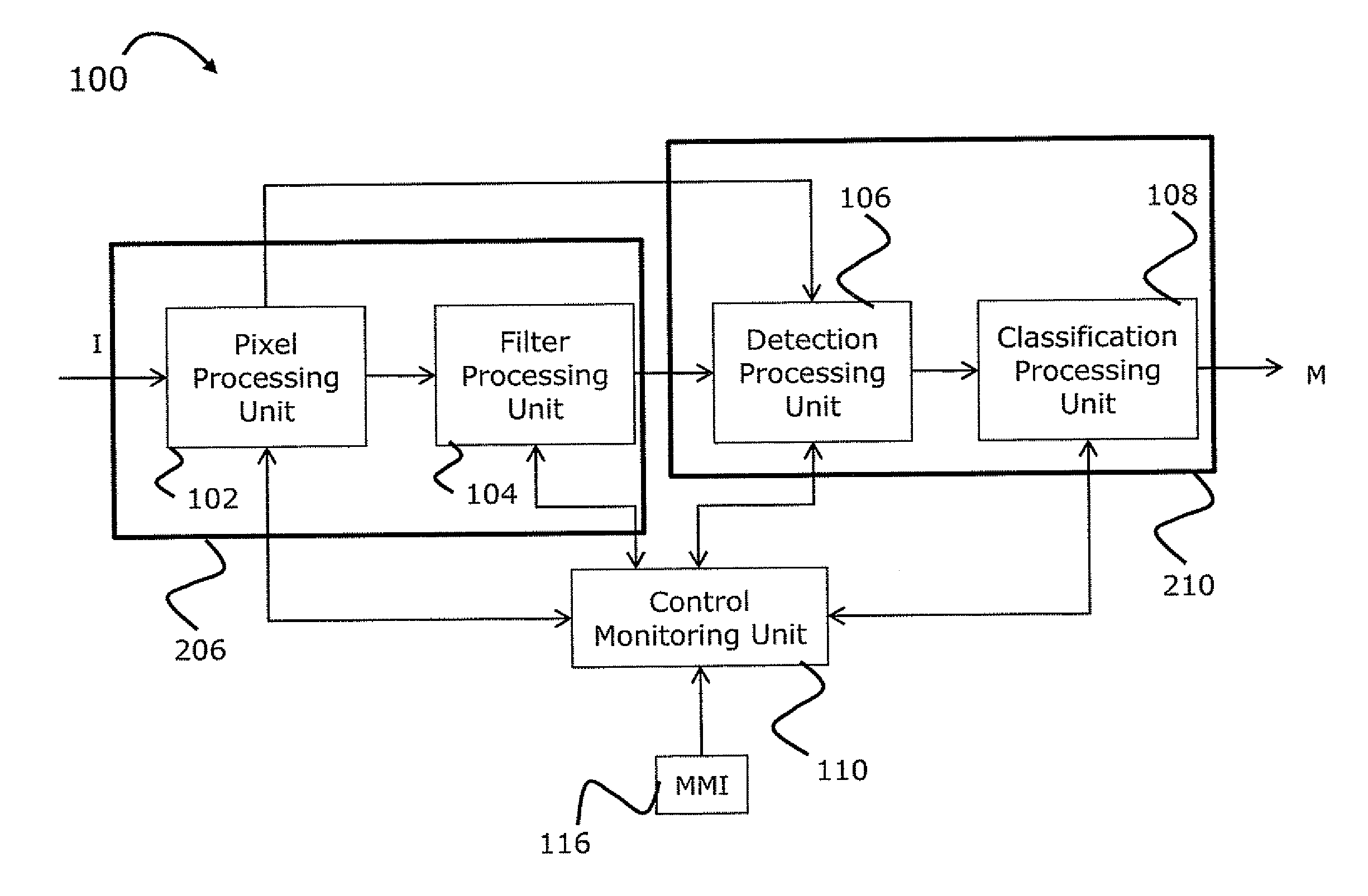
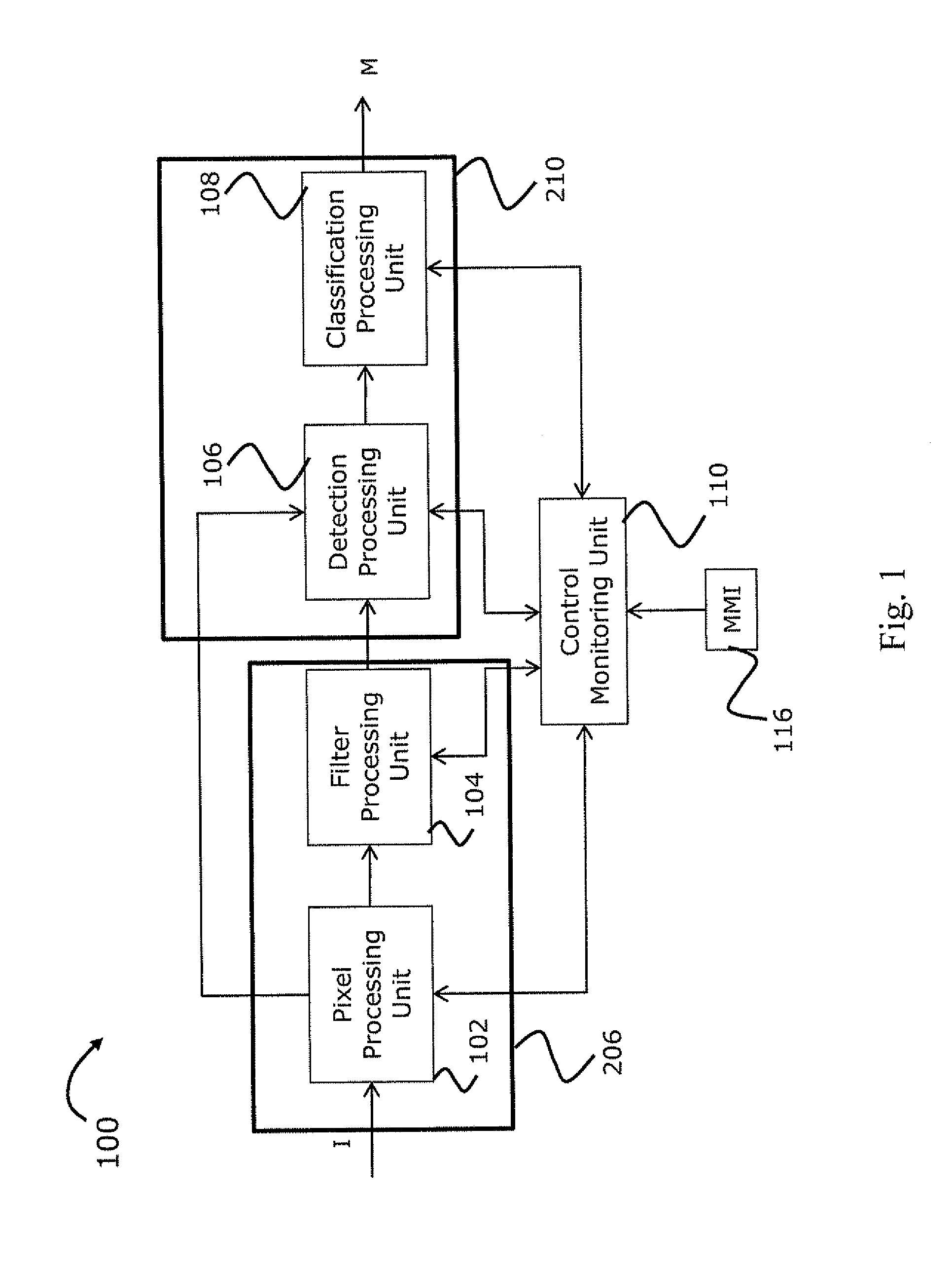
[0045]FIG. 1 depicts an example of an imaging system 100 of the present invention. The system 100 is configured as a computer system capable of receiving and processing input digital data indicative of image data generated (on line or off line) by one or more imagers. The latter may be of any known suitable type, such as optical imager (e.g. camera), or imager based on collection of other type of radiation such as X-ray, ultrasound, etc. The system typically includes a data processing and analyzing utility connected to such other utilities as data input utility, data output utility (e.g. display), and memory utility, which are not specifically shown here. Thus, the system 100 in the figure is illustrated for simplicity by the elements / modules of the data processing and analyzing utility.

[0046]The data processing and analyzing utility 100 is configured and operable for receiving image data (from the data input utility) in an appropriate digital format and processing the image data to...


PUM


Abstract

An imaging system for inspection of a region of interest. The system includes a data processing and analyzing utility responsive to input data indicative of one or more images of a region of interest and identifying one or more objects therein. The data processing and analyzing utility includes a visualization processor utility and a computer aided detection processor connected to the visualization processor utility. The visualization processor utility is configured and operable for receiving the input image data, converting the received image data into a desired representation, and decomposing image data of said desired representation into different components. The computer aided detection processor is configured and operable for scoring said components according to one or more predetermined scoring schemes, and classifying the blobs and contours according to a degree of match with reference data indicative of one or more predetermined objects.

Description

FIELD OF THE INVENTION[0001]This invention generally relates to computer aided imaging techniques for automatic or semi-automatic inspection of a region of interest for identification of one or more objects therein.BACKGROUND OF THE INVENTION[0002]Typically, an image of a region or scene is produced in order to analyze it and extract desired data therefrom. In medical applications, for example, a probe captures images of a region of interest within a patient's body and image data is used for detection of anomalies, such as unhealthy tissue and polyps. In some other applications, image data is inspected to detect anomalies, such as fire, smoke, or pollution.[0003]When imaging cluttered scenes in varying conditions (noise, clutter, dynamic range, dynamic motion), it is often difficult to perceive subtle anomalies and irregularities in such imagery. This is especially true in imaging situations where such conditions cannot be controlled in terms of signal to background, signal to noise...

Claims


Application Information

Patent Timeline
Patent Type & Authority Applications(United States)
IPC IPC(8): G06T7/00
CPCG06T7/0012G06T2207/20104G06T2207/10068G06T7/0081G06T7/11
Inventor GUISSIN, RAMI
Owner D V P TECH
Why Eureka
Try Eureka