Cartridge and unit

Active Publication Date: 2013-05-16
CANON KK
View PDF18 Cites 50 Cited by
  • Summary
  • Abstract
  • Description
  • Claims
  • Application Information

AI Technical Summary

Benefits of technology

[0009]The present invention has been accomplished in view of the above-described circumstances. A principal object of the present invention is to provide a cartridge and a unit which are capable

Problems solved by technology

However, the above-described conventional constitutions were accompanied with the following problems.
That is, the seal member is a soft part and therefore it is difficult to hold the seal member by the automatic machine (robot), so that it is difficult to apply the seal member onto the cartridge frame with high accuracy.
Further, the fixing member such as the double-side tape is similarly a soft strip par

Method used


Image

  • Cartridge and unit
  • Cartridge and unit
  • Cartridge and unit

Examples


embodiment 1

[0032]An image forming apparatus and a process cartridge in this embodiment will be specifically described below with reference to the drawings. In the following description, a longitudinal direction is a direction (rotational axis direction of a photosensitive drum) crossing (substantially perpendicular to) a direction in which the process cartridge is mounted into an image forming apparatus main assembly.

(General Structure)

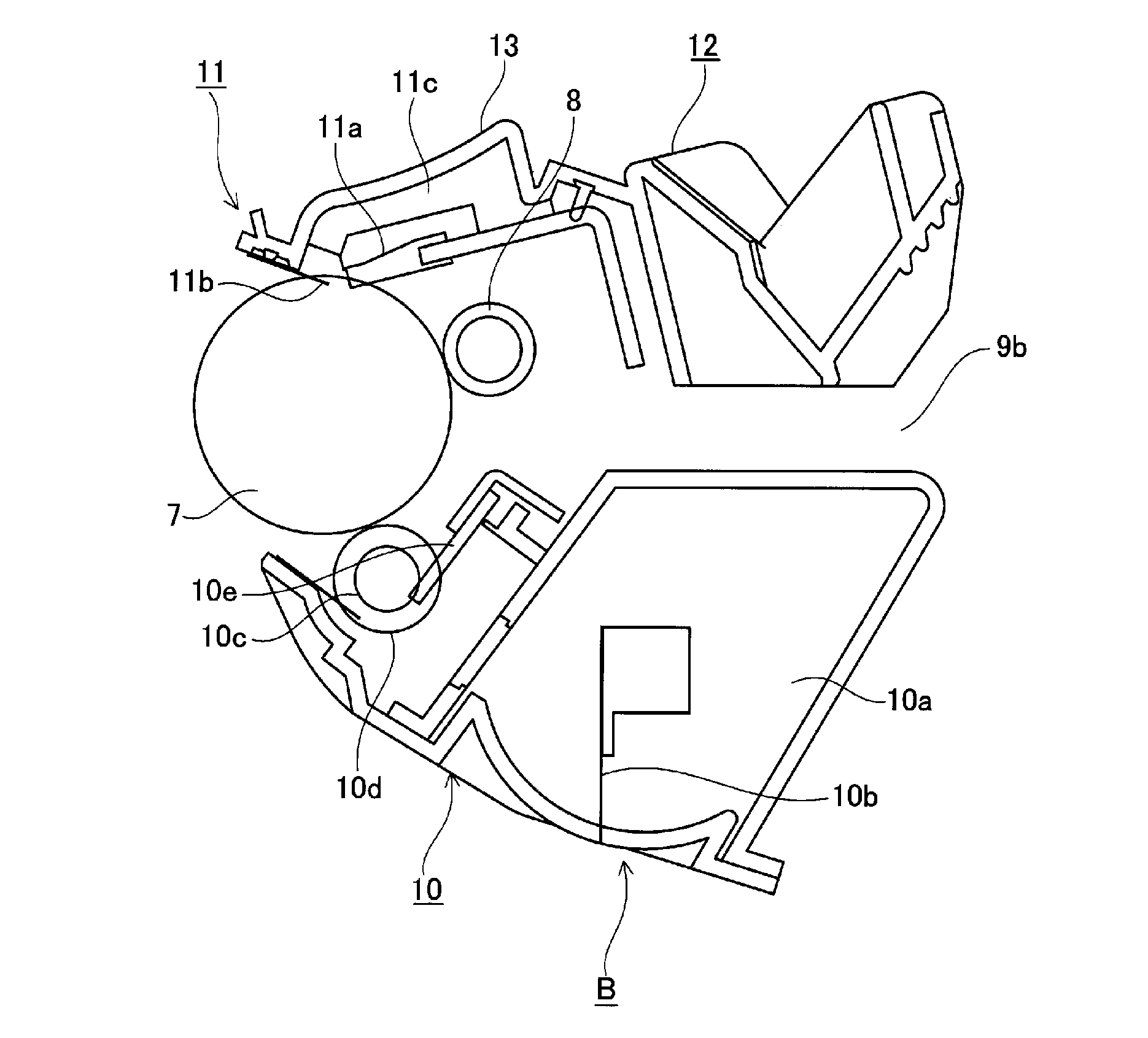
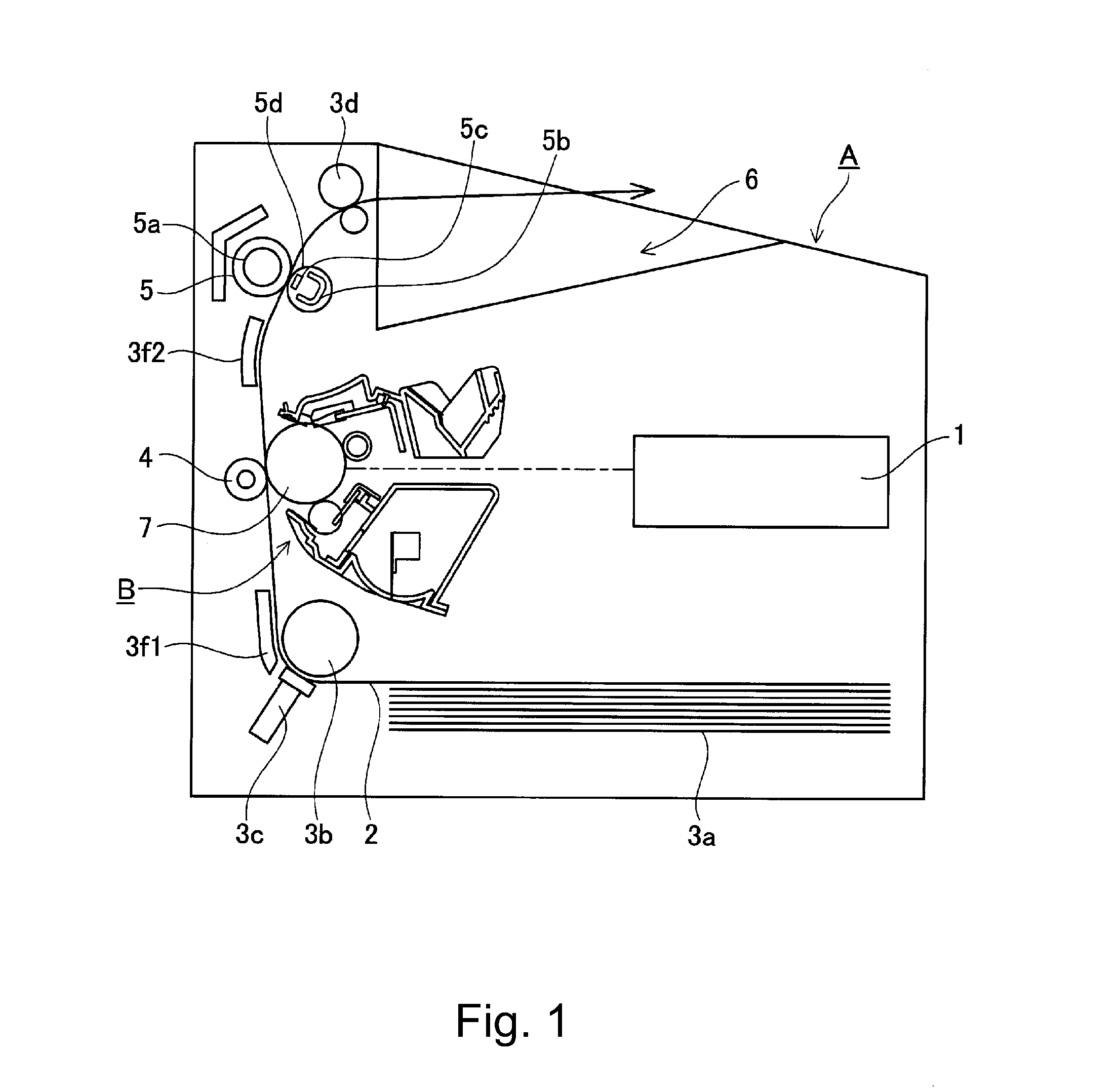
[0033]A general structure of each of the image forming apparatus and the process cartridge will be described with reference to FIGS. 1 and 2. FIG. 1 is a schematic sectional view showing a general structure of a laser beam printer as an example of the image forming apparatus in this embodiment, and FIG. 2 is a schematic sectional view of the process cartridge in this embodiment.

[0034]The general structure of an image forming apparatus main assembly A will be described. First, a drum-shaped electrophotographic photosensitive member (image bearing member, hereinaf...

embodiment 2

[0082]Embodiment 2 will be described. In this embodiment, a constitution portion different from that in Embodiment 1 described above will be described and a similar constitution portion will be omitted from description thereof.

[0083]FIG. 13 is a schematic sectional view showing a state in which the resin materials are injected for molding into the cleaning container, and FIG. 14 is a schematic sectional view showing a state in which the resin materials are injected for molding into the cleaning container.

[0084]In this embodiment, a constitution in which the resin materials are directly injected for molding from the mold contact surface side of the cleaning container 13 into the cleaning container 13 to form the plurality of members is employed. By employing such a constitution, the plurality of members are provided with injection ports (gates) into which the resin materials are to be directly injected from the molds when they are molded. A form in which the resin materials are direc...

embodiment 3

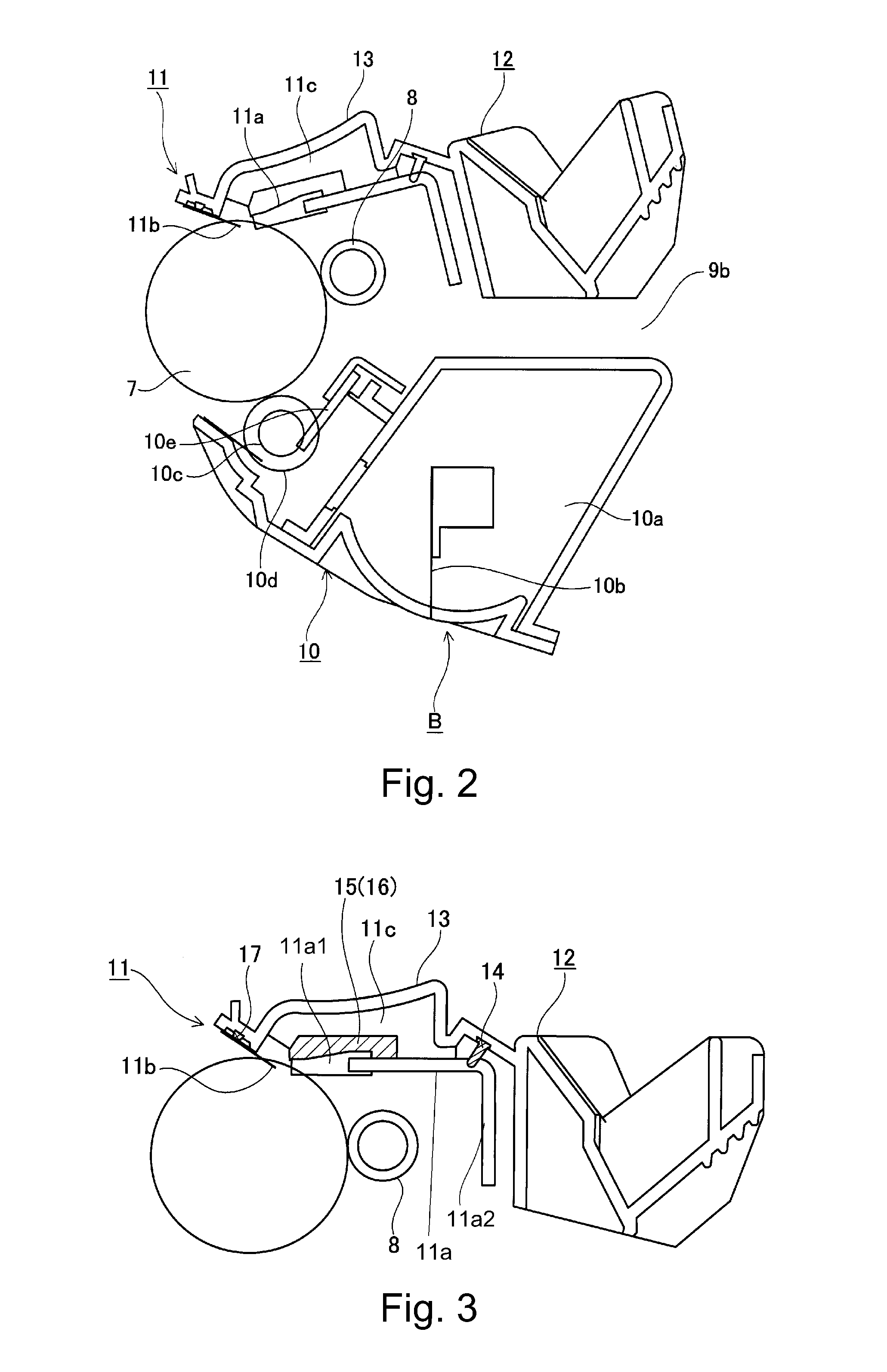
[0093]FIG. 15 is a schematic sectional view of a process cartridge in Embodiment 3. In this embodiment, a constitution portion different from that in Embodiments 1 and 2 described above will be described and a similar constitution portion will be omitted from description thereof.

[0094]In Embodiment 1 described above, the example in which the under-blade seal 14, the vertical seals 15 and 16, the fixing member 17 and the electrode member 18 are provided in the photosensitive drum unit 11 by using the elastomer resin materials. However, these members may also be provided in the developing unit 10.

[0095]That is, the above members may also be members, for preventing the toner from leaking out from a gap between a developing blade 10e and a developing frame 10g constituting a toner accommodating portion a of the developing unit 10, such as an under-blade seal 114 extending in the longitudinal direction of the developing unit 10 and a vertical seal 115 provided at longitudinal end portion...


PUM


Abstract

A cartridge detachably mountable to a main assembly of an image forming apparatus includes a cartridge frame formed of a resin material; a plurality of resin members molded on the cartridge frame by injection molding of a resin material different from that of the cartridge frame; a plurality of contact surfaces, provided on the cartridge frame, to which metal molds corresponding to the resin members are to be contacted from the same side when the resin members are molded; and a plurality of resin material inlet ports, provided in an opposite side of said cartridge frame from a side where the contact surfaces are provided. The resin material has been flowed into the cartridge frame when the resin members are molded.

Description

FIELD OF THE INVENTION AND RELATED ART[0001]The present invention relates to a cartridge detachably mountable to an electrophotographic image forming apparatus main assembly and a unit for use with the electrophotographic image forming apparatus main assembly.[0002]In a conventional electrophotographic image forming apparatus using an electrophotographic image forming process, an electrophotographic photosensitive member and a process member acting on the electrophotographic photosensitive member are integrally assembled into a unit to prepare a process cartridge. Further, a type in which the process cartridge is detachably mountable to the image forming apparatus main assembly is employed.[0003]In such a process cartridge, in order to prevent a developer (toner) accommodated in the process cartridge from leaking out to an outside, the process cartridge is configured to seal between cartridge frames and between parts, for constituting the process cartridge, with a plurality of seal ...

Claims


Application Information

Patent Timeline
IPC IPC(8): G03G15/08
CPCG03G15/0898G03G2215/0872G03G21/181
Inventor HOSHI, NOBUHARUSUZUKITAKARADA, HIROSHIYAMASAKI, TOSHITERU
Owner CANON KK
Why Eureka
Try Eureka