Sound insulation structure of internal combustion engine

a technology of internal combustion engine and sound insulation structure, which is applied in the direction of casings, fuel injection devices, feed systems, etc., can solve the problem that the sound insulation cover cannot be arranged in such a narrow region without difficulty, and achieve the effect of lowering the temperature of the sound insulation member, reducing the temperature of the surrounded space, and reducing the temperature of the fuel injection devi

Inactive Publication Date: 2010-10-07
TOYOTA JIDOSHA KK
View PDF9 Cites 2 Cited by
  • Summary
  • Abstract
  • Description
  • Claims
  • Application Information

AI Technical Summary

Benefits of technology

[0010]Further preferably, a gap is formed between the intersection region and the sound insulation member. Since an air flows through this gap, this structure can lower a temperature of the sound insulation member adjoining the gap, and can lower a temperature of the surrounded space. Consequently, the temperature of the fuel injection device arranged in the surrounded space can be lowered to prevent vaporization of the fuel in the fuel injection device.
[0011]Preferably, the sound insulation structure of the internal combustion engine further includes a cylinder head arranged on the right and left banks, and a gasket arranged between the cylinder head and the first and second intake pipes, and the gasket is integral with the sound insulation member. This structure can suppress transmission of a heat from the cylinder head to the first and second intake pipes. Therefore, it is possible to suppress increase in temperature of the surrounded space, and therefore to suppress the vaporization of fuel in the fuel injection device arranged in the surrounded space.
[0012]More preferably, the sound insulation member is formed of urethane foam. Since the urethane foam has a good sound insulation property and is light and flexible, it can be worked or processed easily.
[0013]Preferably, the sound insulation member is arranged in contact with the fuel injection device. In this structure, the sound insulation member in contact with the fuel injection device can absorb more reliably the sound generated by the fuel injection device.
[0014]Preferably, the sound insulation member is engaged between the plurality of first and second intake pipes. The first and second intake pipes can be attached to another member such as a cylinder head while holding the engaged sound insulation member between the first and second intake pipes, and this structure can improves an assembly property.
[0015]The invention can provide the sound insulation structure of the internal combustion engine having an improved sound insulation performance.

Problems solved by technology

In a V-type engine, a fuel injection device is arranged in a narrow region between right and left banks, and prior arts have suffered from a problem that a sound insulation cover cannot be arranged in such a narrow region without difficulty.

Method used


Image

  • Sound insulation structure of internal combustion engine
  • Sound insulation structure of internal combustion engine
  • Sound insulation structure of internal combustion engine

Examples


first embodiment

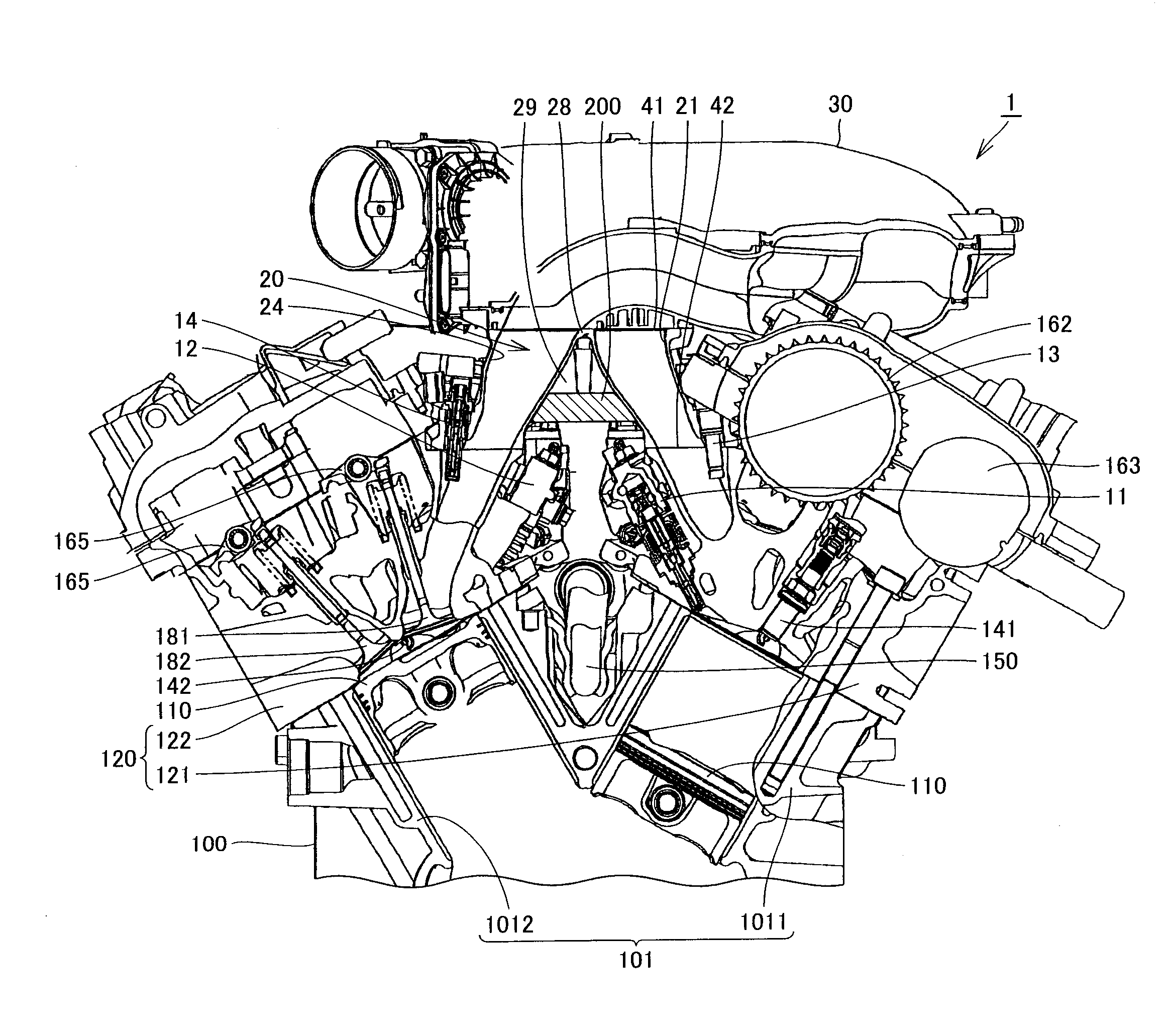
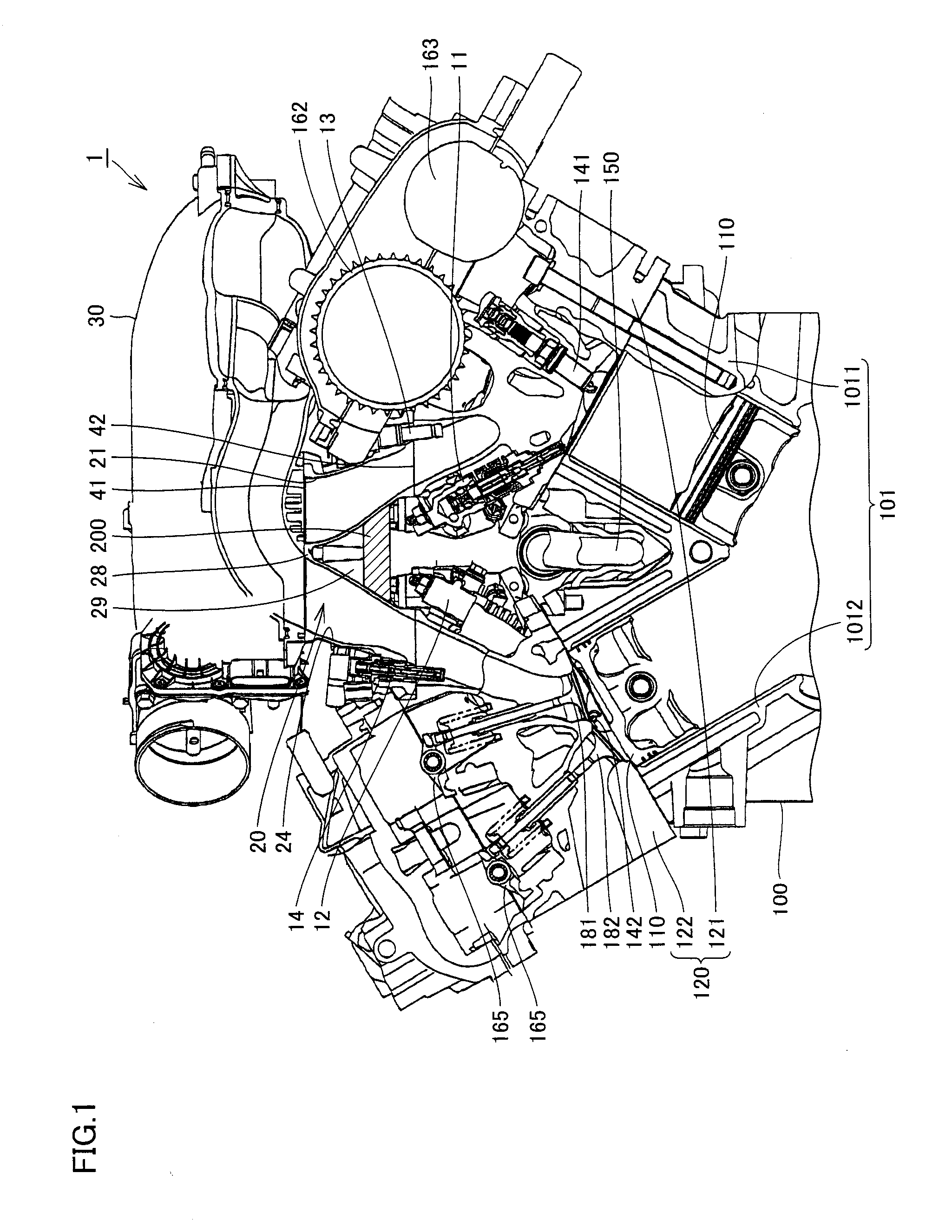
[0028]FIG. 1 is a cross section of a sound insulation structure of an internal combustion engine according to a first embodiment of the invention. Referring to FIG. 1, a sound insulation structure 1 of the internal combustion engine according to the first embodiment of the invention includes in-cylinder injection injectors 11 and 12 that are fuel injection devices and supply a fuel to an engine 100, i.e., the internal combustion engine, an intake manifold 20 that is an intake pipe structure made of metal and supplies a gas to engine 100, and a surge tank unit 30 that is an intake pipe structure made of plastic and is coupled to intake manifold 20.

[0029]Engine 100 has a cylinder block 101, in which a piston 110 is arranged. Piston 110 is connected to a crankshaft by a connecting rod.

[0030]Cylinder block 101 has right and left banks 1011 and 1012, which intersect together with a predetermined angle therebetween. The angle between right and left banks 1011 and 1012 is merely required t...

second embodiment

[0050]FIG. 10 is a cross section of a sound insulation structure of an internal combustion engine according to a second embodiment of the invention. Referring to FIG. 10, sound insulation structure 1 of the internal combustion engine according to the second embodiment of the invention differs from sound insulation structure 1 of the internal combustion engine according to the first embodiment in that sound insulation member 200 reaches intersection region 28. Since sound insulation member 200 reaches intersection region 28, sound insulation member 200 has a triangular form (i.e., a triangular prism form).

third embodiment

[0051]FIG. 11 is a cross section of a sound insulation structure of an internal combustion engine according to a third embodiment of the invention. Referring to FIG. 11, sound insulation member 200 according to the third embodiment of the invention is integral with gasket 210. Further, sound insulation member 200 is in direct contact with in-cylinder injection injectors 11 and 12. Sound insulation member 200 is not required to satisfy both the condition that it is integral with gasket 210 and the condition that it is in contact with in-cylinder injection injectors 11 and 12. For example, sound insulation member 200 that is integral with gasket 210 may not be in contact with in-cylinder injection injectors 11 and 12. Conversely, sound insulation member 200 that is in contact with in-cylinder injection injectors 11 and 12 may not be integral with gasket 210.

[0052]In sound insulation structure 1 of the internal combustion engine according to the third embodiment of the invention that h...


PUM


Abstract

Provided is a sound insulation structure of an internal combustion engine capable of preventing propagation of a sound generated by an injector into an interior of a vehicle. The sound insulation structure of the internal combustion engine includes a V-type cylinder block having a right bank and a left bank; a right bank intake pipe supplying a gas to the right bank; a left bank intake pipe supplying the gas to the left bank and intersecting the right bank intake pipe; in-cylinder injection injectors arranged in a surrounded space surrounded by the right and left banks and the intake pipes; and a sound insulation member arranged in the surrounded space between the in-cylinder injection injectors and an intersection region.

Description

TECHNICAL FIELD[0001]The invention relates to a sound insulation structure of an internal combustion engine, and particularly to a sound insulation structure of an internal combustion engine for shutting off sounds generated by a fuel injection device.BACKGROUND ART[0002]A sound insulation structure of an internal combustion engine has been disclosed, e.g., in Japanese Patent Laying-Open No. 2000-179351 (Patent Reference 1).DISCLOSURE OF THE INVENTION[0003]The patent reference 1 has disclosed a structure in which a sound insulation cover is arranged around a direct-injection fuel infection valve located outside an engine body.[0004]In a V-type engine, a fuel injection device is arranged in a narrow region between right and left banks, and prior arts have suffered from a problem that a sound insulation cover cannot be arranged in such a narrow region without difficulty.[0005]Accordingly, the invention has been made for overcoming the above problem, and an object of the invention is t...

Claims


Application Information

Patent Timeline
Patent Type & Authority Applications(United States)
IPC IPC(8): F02B77/13
CPCF02B77/13F02M69/045F02F7/008F02F7/0012F02B75/22F02B77/11F02M61/16
Inventor FUKAMI, KASHIROUKAWAGUCHI, KOUJI
Owner TOYOTA JIDOSHA KK
Why Eureka
Try Eureka