Battery case

a battery and case technology, applied in the field of battery cases, can solve the problems of limiting weight reduction, reducing strength, and serious danger to drivers and passengers, and achieve the effects of reducing weight, ultra-high strength, and high deformation resistan

Pending Publication Date: 2022-01-27
POHANG IRON & STEEL CO LTD
View PDF0 Cites 0 Cited by
  • Summary
  • Abstract
  • Description
  • Claims
  • Application Information

AI Technical Summary

Benefits of technology

[0010]As described above, according to the present disclosure, by forming a shock absorption part on the lateral frame itself of the battery case, high deformation resistance against an impact load on the side surface may be secured, and at the same time, ultra-high strength steel of about 980 MPa or more can be applied to the battery case, such that there is an effect that can secure additional weight reduction.
[0011]In addition, according to the present disclosure, when a steel material is applied to a battery case, assembly properties can be significantly improved as compared to the case of a method of bonding a reinforcing member in the related art, and costs related to molding, processes, and the like, can be significantly reduced by dramatically reducing the number of parts.

Problems solved by technology

A battery installed in a vehicle such as an electric vehicle or a hybrid vehicle may lead to fire and explosion in an event of a vehicle collision, resulting in a serious danger to drivers and passengers.
When formed of an extruded material of aluminum, a reinforcing member can be easily manufactured in various shapes, but it is relatively expensive and has lower strength than the steel material, so that the thickness thereof becomes thicker, thereby limiting weight reduction.
Meanwhile, in the case of a steel material, an ultra-high strength material having a tensile strength of about 980 MPa or more is applied to reduce weight, and such an ultra-high strength material has a problem that is difficult to form and many springbacks may occur.
In order to improve springback, several or dozens of correction times are required, and in some cases, there is a problem in that assembly is not easy due to inconsistent parallelism between components.

Method used


Image

  • Battery case
  • Battery case
  • Battery case

Examples


Embodiment Construction

[0017]Hereinafter, the present disclosure will be described in detail. In adding reference numerals to elements of each drawing, it should be noted that the same elements are assigned the same numerals as possible even if they are indicated on different drawings. In addition, in describing the present invention, when it is determined that a detailed description of a related known configuration or function may obscure the subject matter of the present disclosure, a detailed description thereof will be omitted.

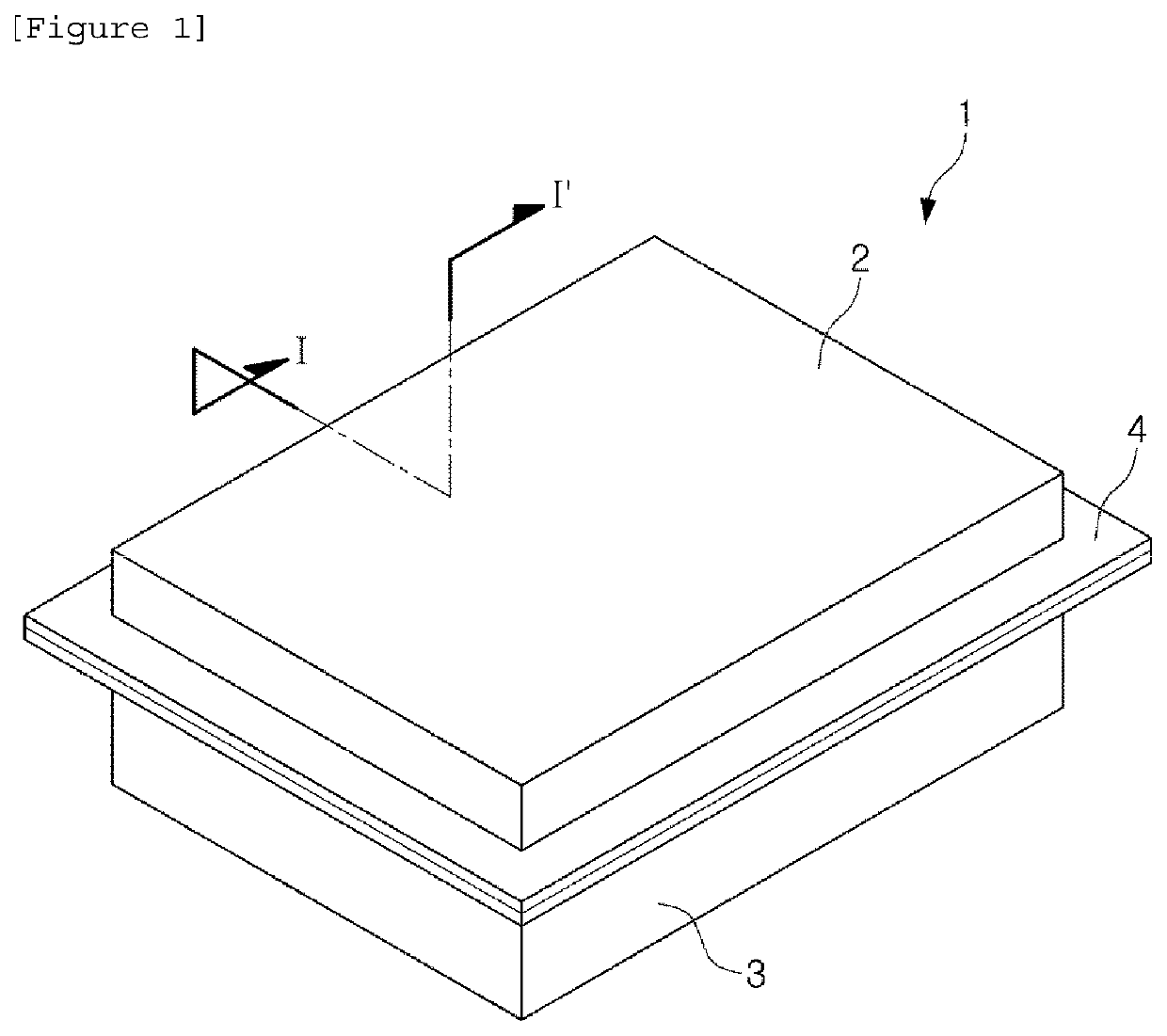
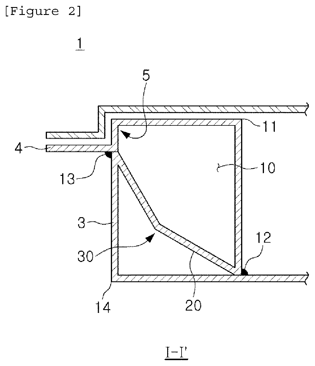
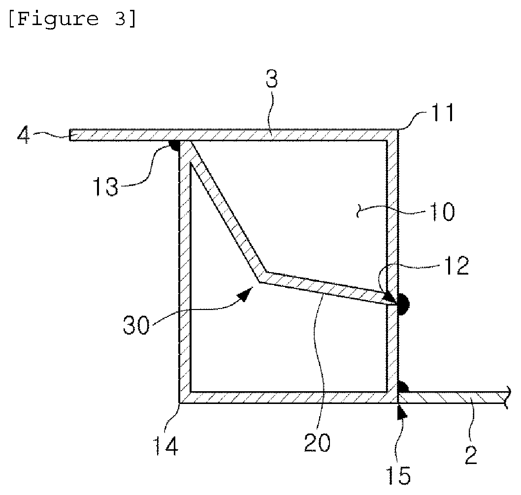
[0018]FIG. 1 is a perspective view of a battery case, and FIG. 2 is a cross-sectional view taken along line A-A of FIG. 1 and is a cross-sectional view of a lateral frame of a battery case according to an embodiment of the present disclosure.

[0019]According to an embodiment of the present disclosure, a battery case includes a case body 1 having a plate 2 and a lateral frame 3 surrounding the plate, wherein the lateral frame 3 includes a first side wall and a second side wall hav...


PUM

PropertyMeasurementUnit
tensile strengthaaaaaaaaaa
angleaaaaaaaaaa
rectangular shapeaaaaaaaaaa

Abstract

The present invention relates to a battery case which is made from a steel material, thereby providing a cross-section similar to that of an extruded material and having improved impact resistance properties, and at the same time, enabling the reduction of costs through the integration of components, the battery case comprising a case main body having a plate and a lateral frame enclosing the plate, wherein the lateral frame comprises a hollow part inside thereof, a reinforcement part which traverses the hollow part at a portion between side walls on both sides, or protrudes into the hollow part from at least one of the side walls, and a shock absorption part which is formed by the reinforcement part being bent or curved.

Description

TECHNICAL FIELD[0001]The present disclosure relates to a battery case made of a steel material and capable of improving impact resistance properties.BACKGROUND ART[0002]A battery installed in a vehicle such as an electric vehicle or a hybrid vehicle may lead to fire and explosion in an event of a vehicle collision, resulting in a serious danger to drivers and passengers. In order to prevent this, a reinforcing member is provided in the battery itself, in addition to a collision reinforcing member of a vehicle body to prepare for a collision accident.[0003]The reinforcing member of the battery can be mainly assembled inside or outside of the battery case.[0004]For example, when aluminum is applied, a side wall itself of the battery case may be formed of an extruded material, and in the case of a steel material, a reinforcing member is bonded to an inside of the battery case.[0005]When formed of an extruded material of aluminum, a reinforcing member can be easily manufactured in vario...

Claims


Application Information

Patent Timeline
Patent Type & Authority Applications(United States)
IPC IPC(8): H01M50/119H01M50/242H01M50/224H01M50/204H01M50/227H01M50/249
CPCH01M50/119H01M50/224H01M50/242Y02E60/10H01M50/207H01M50/249H01M50/276H01M2220/20H01M50/204H01M50/227H01M50/20H01M50/116
Inventor CHUNG, GI-SUKWEE, SANG-KWONKIM, DON-GUN
Owner POHANG IRON & STEEL CO LTD
Why Eureka
Try Eureka