
Drum brake apparatus for vehicle

Active Publication Date: 2020-07-09
HYUNDAI MOBIS CO LTD
View PDF0 Cites 0 Cited by
  • Summary
  • Abstract
  • Description
  • Claims
  • Application Information

AI Technical Summary

Benefits of technology

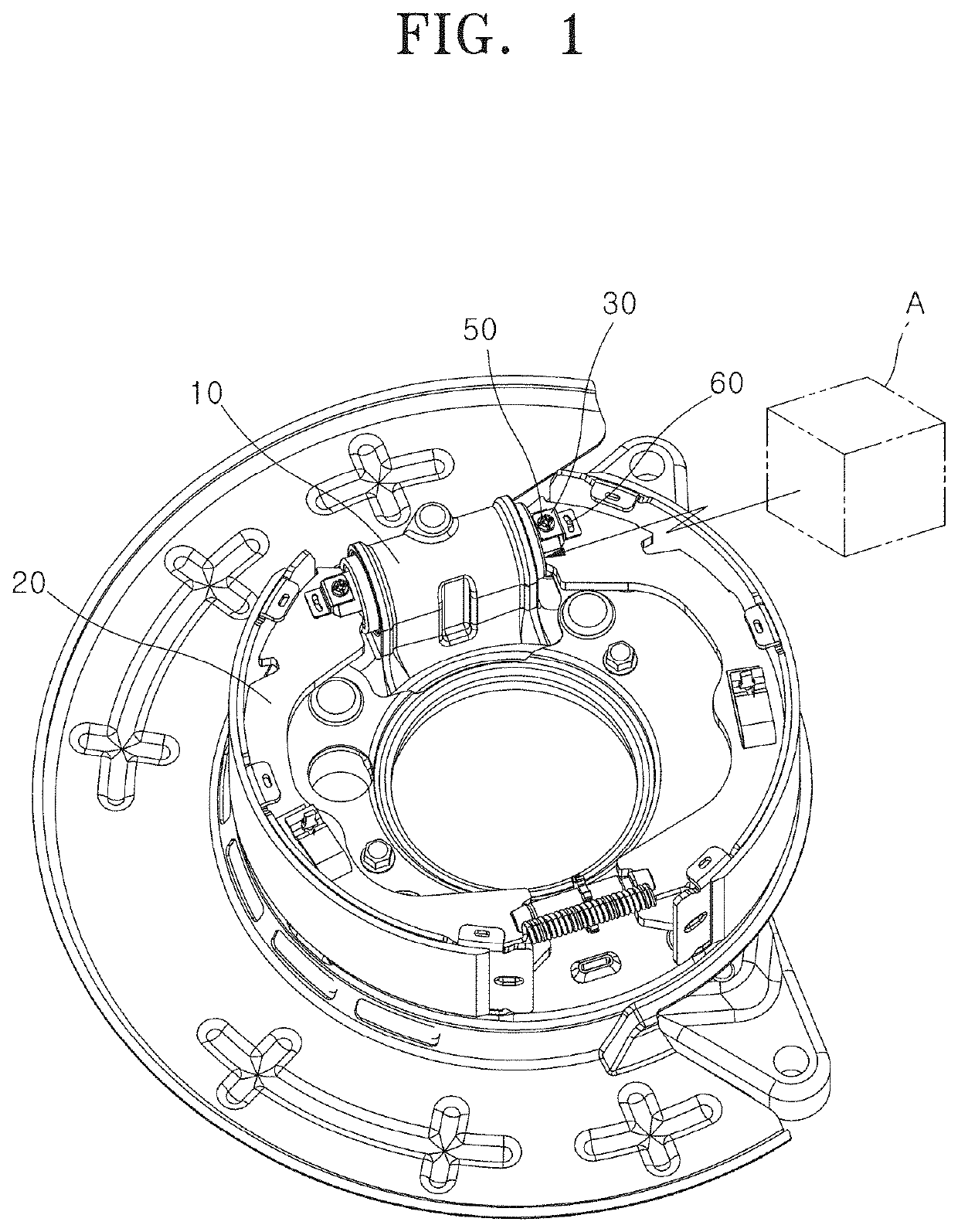
This patent is about a new drum brake system for vehicles that eliminates the need for a separate return spring. Instead, the brakes are designed to automatically return the shoes to their original position when the cylinders are operated. This design simplifies the assembly process and allows for more flexibility in design, which can improve the performance of the vehicle. Additionally, it removes the need for a separate space between the shoes, allowing for the use of more vehicle parts and upgrading them.

Problems solved by technology

In this case, there is a limitation in improving the performance of the vehicle.

Method used


Image

  • Drum brake apparatus for vehicle
  • Drum brake apparatus for vehicle
  • Drum brake apparatus for vehicle

Examples


Embodiment Construction

[0029]Hereafter, a drum brake apparatus for a vehicle in accordance with an embodiment of the present invention will be described in detail with reference to the accompanying drawings. It should be noted that the drawings are not to precise scale and may be exaggerated in thickness of lines or sizes of components for descriptive convenience and clarity only. Furthermore, the terms as used herein are defined by taking functions of the invention into account and can be changed according to the custom or intention of users or operators. Therefore, definition of the terms should be made according to the overall disclosures set forth herein.

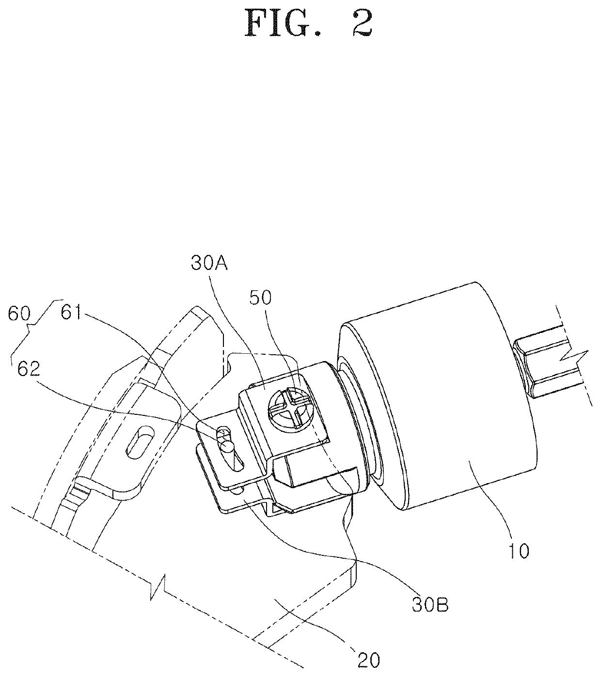
[0030]FIG. 1 is a perspective view schematically illustrating a drum brake apparatus for a vehicle in accordance with an embodiment of the present invention, and FIG. 2 is an expanded view of main parts of FIG. 1.

[0031]Referring to FIGS. 1 and 2, the drum brake apparatus for a vehicle in accordance with the embodiment of the present invention may incl...


PUM


Abstract

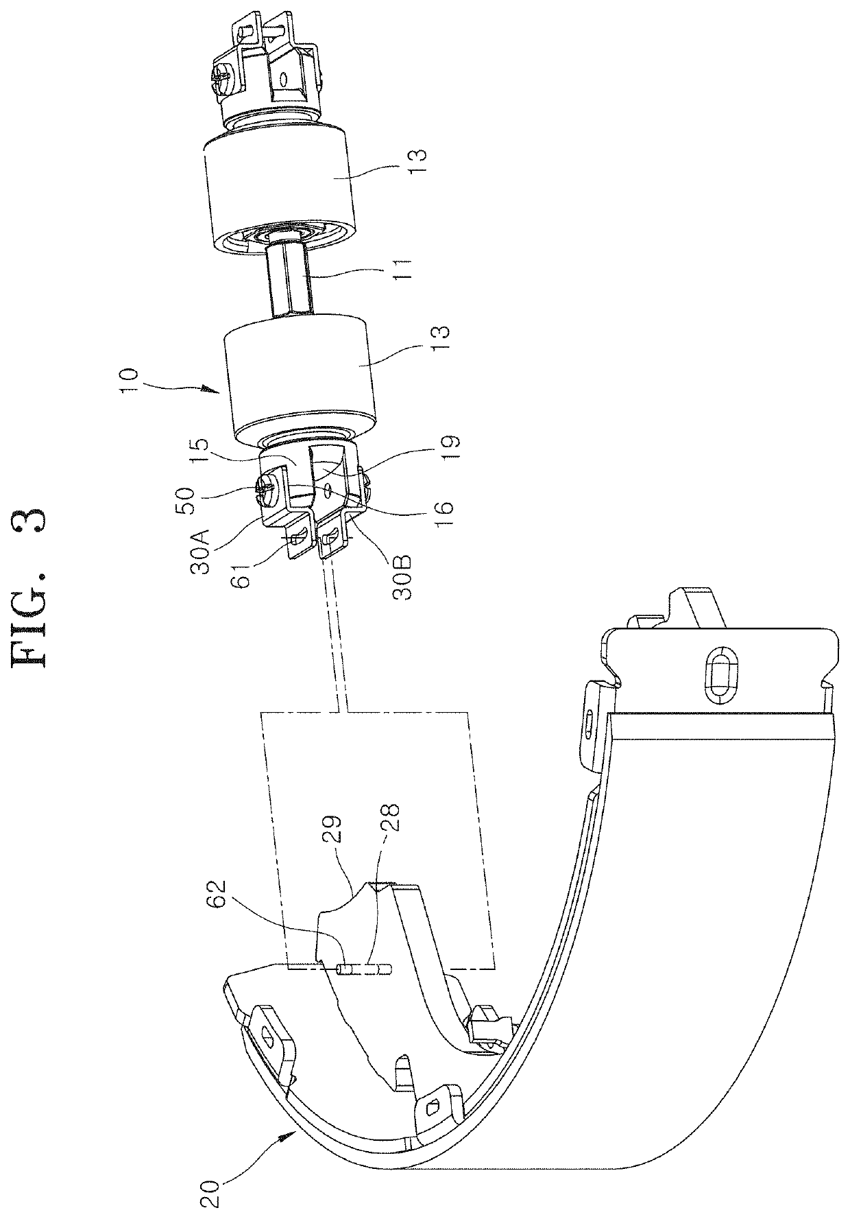
A drum brake apparatus for a vehicle may include: a cylinder device configured to apply a braking force to a shoe; a clip part extended from the cylinder device toward the shoe, and elastically contacting the shoe; a cylinder coupling part coupling the clip part to the cylinder device; and a shoe assembling part fastening the clip part to the shoe.

Description

CROSS-REFERENCES TO RELATED APPLICATIONS[0001]The present application claims priority to Korean application number 10-2019-0000598, filed on Jan. 3, 2019, which is incorporated by reference in its entirety.BACKGROUND OF THE INVENTION[0002]The present invention relates to a drum brake apparatus for a vehicle, and more particularly, to a drum brake apparatus for a vehicle, which can move shoes in connection with an operation of a cylinder device.[0003]In general, a drum brake of a vehicle includes a drum rotated with a wheel, a pair of shoes disposed on a back plate so as to face the inner circumferential surface of the drum and having a friction material attached to the outer circumference thereof, and a wheel cylinder for transferring a braking force to the shoes. When the drum brake is operated, the pair of shoes are pushed by the wheel cylinder and expanded and moved in a direction away from each other. Then, when the wheel cylinder is returned to the initial position, the pair of...

Claims


Application Information

Patent Timeline
IPC IPC(8): B60T1/06F16D51/22B60T13/02
CPCF16D2125/40B60T1/067F16D51/22B60T13/02F16D65/22F16D2121/04F16D2125/04F16D51/24F16D65/09F16D51/60
Inventor JUNG, MIN KYU
Owner HYUNDAI MOBIS CO LTD
Learn More