Manufacturing of holemaking tools

a holemaking tool and manufacturing technology, applied in the field of process for producing tools, can solve the problems of affecting the surface affecting the quality of machined workpieces, and difficulty in transportation of chips, so as to achieve simple and cost-effective production, long service life, and avoid peeling.

Active Publication Date: 2013-05-16
KENNAMETAL INC
View PDF19 Cites 21 Cited by
  • Summary
  • Abstract
  • Description
  • Claims
  • Application Information

AI Technical Summary

Benefits of technology

[0012]Against this background, an object of the present invention is based on making possible a tool which can be produced simply and cost-effectively, in particular a fine machining tool and preferably a combined tool, such as a drilling / reaming tool, which is distinguished by a good wear resistance and a long service life without the risk of a peeling-off coating.
[0016]This measure achieves the particular advantage that, on the one hand, the base coating achieves a high wear resistance, but at the same time only a fine coating is applied in the region of the blade, so that the risk of the coating peeling away is avoided.
[0017]The specially chosen production process, according to which initially the entire main body is provided with the base coating, while subsequently, in the second step, it is partially removed again by a grinding operation in the region of the relevant blades for the fine machining and subsequently, in the third step, the fine coating is again applied, makes it possible to obtain a production process which is simple overall.
[0018]In an expedient development, it is provided in this respect that the blade is only incorporated, in particular ground, in the main body after application of the base coating. This means that the blade provided at the end with the fine coating is only ground once, to be precise after application of the base coating, and thereby formed for the first time, thereby keeping down the complexity that production involves.
[0019]Expediently, the fine coating has in this case a smaller layer thickness than the base coating, in particular a layer thickness smaller by a factor of 2 to 10. The layer thickness of the fine coating is in this case preferably approximately 1 to 2 μam. This avoids, at least to a great extent, the risk of lug formation in the region of the cutting edge of the blade, and consequently the risk of a peeling off of the coating during operation.
[0021]With a view to a production process which is as simple as possible, partial regions of the main body are not covered when the coatings are applied. This has the effect on the finished tool that the fine coating also extends at least into partial regions over the base coating and overlaps it. Usually, the entire main body—completely coated apart from a chucking shank with which the tool is received in a tool receptacle of a machine tool—is completely coated. The fine coating therefore extends over the entire main body, possibly with the exception of the chucking shank. The base coating likewise extends over the entire main body with the exception of the chucking shank and with the exception of the regions which have been ground again after the application of the base coating.

Problems solved by technology

Here it must be avoided in particular that a chip becomes caught between the wall of the hole and the tool, which would result in the machined wall of the hole becoming damaged.
At the same time, the transporting away of the chips becomes more difficult as the depth of the drilled hole increases.
Such roundings are disadvantageous in the case of fine machining tools, such as for example reaming tools, and have an adverse effect on the surface quality of the machined workpiece.
There is also the risk of such a thick coating in the region of the cutting edge being damaged and peeling off during the cutting operation.

Method used


Image

  • Manufacturing of holemaking tools
  • Manufacturing of holemaking tools
  • Manufacturing of holemaking tools

Examples


Embodiment Construction

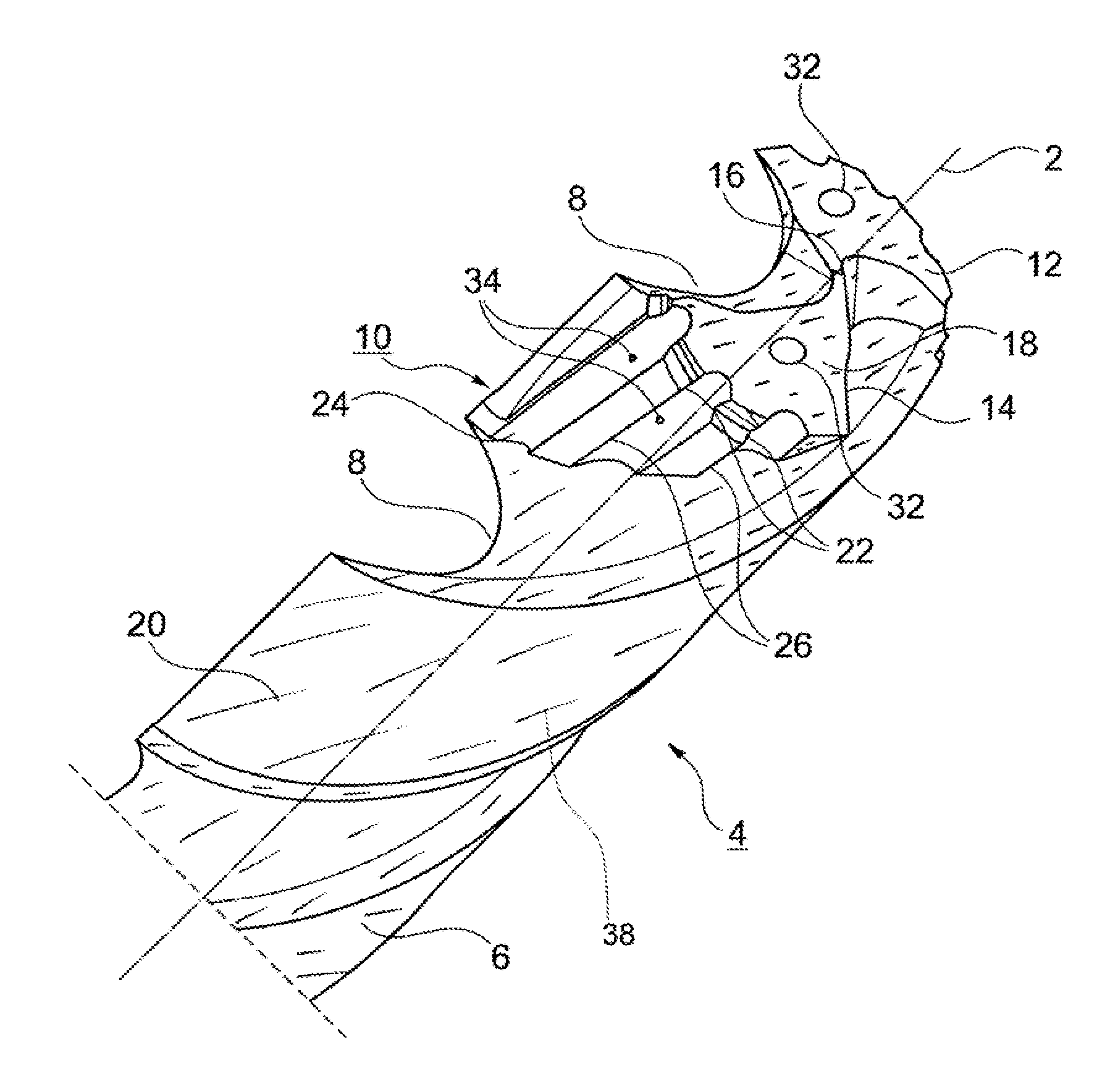
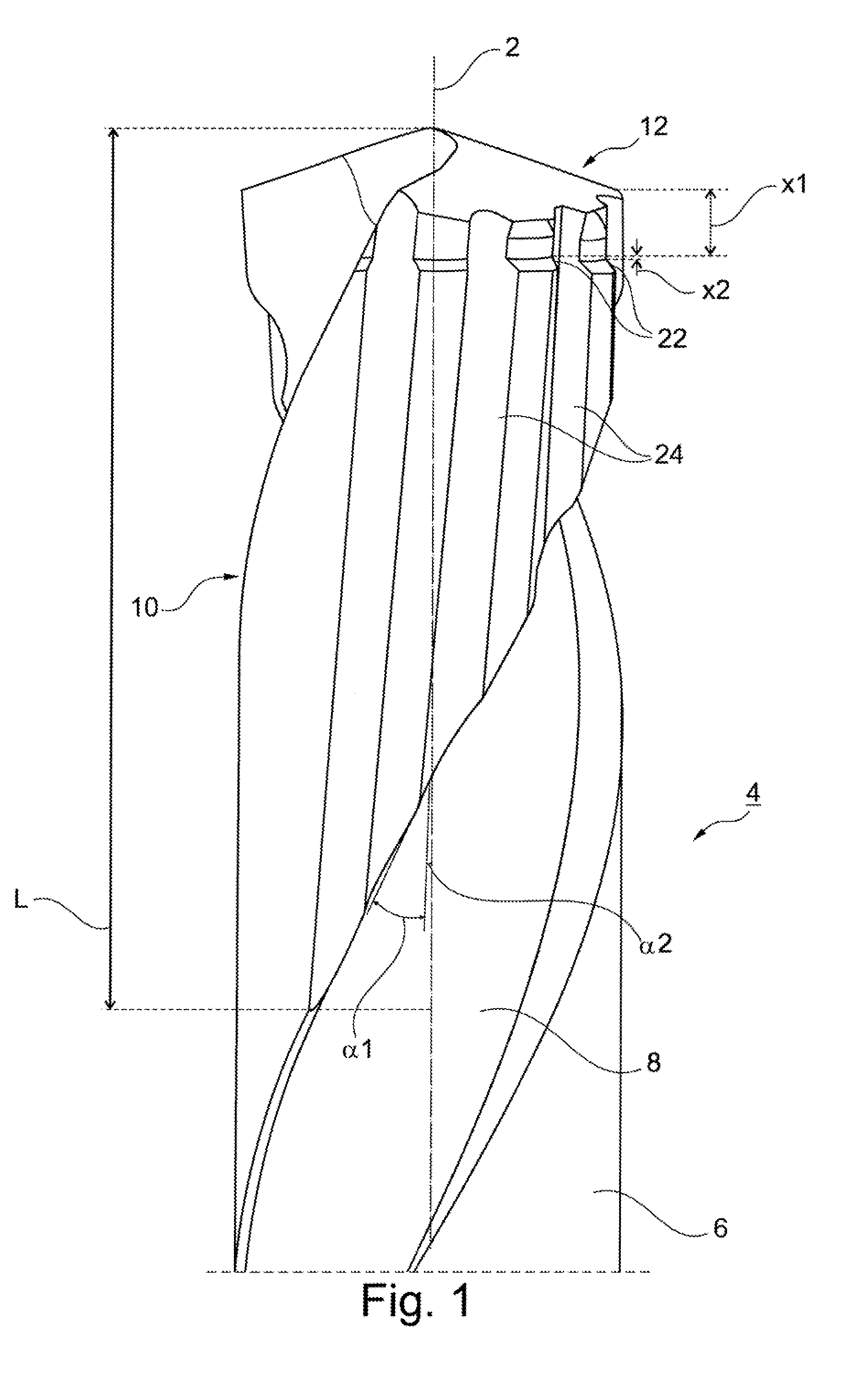
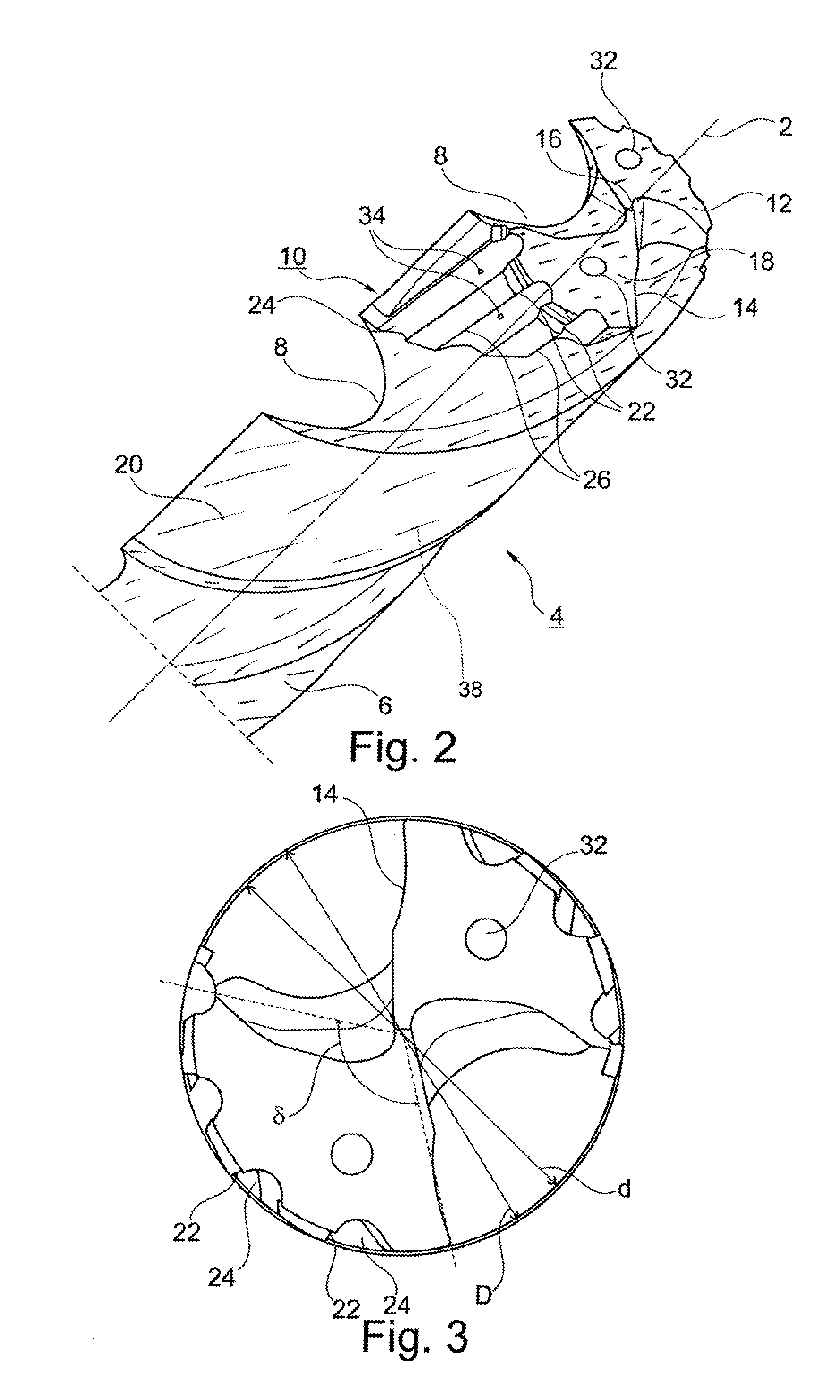
[0046]A drilling / reaming tool 4, which extends in the longitudinal direction 2, hereafter tool for short, has a main body 6, which extends in the longitudinal direction 2 and incorporated in which are main chip flutes 8, two in the exemplary embodiment, which are spiraled at a first twist angle α1. In the forward region, the tool 4 has a reaming head 10. On its end face, the reaming head 10 is formed as a drilling tip 12, which in the exemplary embodiment has two main blades 14 (cf. FIG. 3), which are joined to one another in the drilling center by way of a center line 16. In the circumferential direction, the respective main blade 14 is adjoined by a clearance face 18, which in the exemplary embodiment is formed like the envelope of a cone, respectively extends up to the main chip flute 8 and is assigned to the next-following main blade 14. The fluted region of the main body 6 is additionally adjoined by a shank (not represented), by which the tool 4 is clamped in a tool receptacle...


PUM

PropertyMeasurementUnit
thicknessaaaaaaaaaa
thicknessaaaaaaaaaa
diameteraaaaaaaaaa

Abstract

A process for producing a tool having a main body which extends in a longitudinal direction and at least one blade for machining a workpiece includes providing a base coating on the tool; grinding the at least one blade in a manner that removes the base coating in the region of the at least one blade; and providing a second, fine coating, to the at least one ground blade.

Description

BACKGROUND[0001]1. Field of the Invention[0002]The invention relates to a process for producing a tool which is provided with at least one blade and is intended for the machining of a workpiece. More particularly, the invention relates to a process for producing a reaming tool and preferably for producing a drilling / reaming tool. The invention also relates to a tool produced in particular by this process, in particular a drilling / reaming tool.[0003]2. Background Information[0004]A drilling / reaming tool is disclosed, for example, by DE 101 44 241 B4. The drilling / reaming tool described therein has two main (drilling) blades, which are respectively assigned a spiraled main chip flute, which is incorporated in a main body of the tool. Additionally provided circumferentially are three reaming blades, which are spaced apart from one another in the circumferential direction and protrude in the radial direction somewhat beyond the main blades. The reaming blades in this case directly adjoi...

Claims


Application Information

Patent Timeline
Patent Type & Authority Applications(United States)
IPC IPC(8): B23D77/00B23B51/08
CPCB23B51/08B23D77/00B23P15/32Y10T408/9065B23B2228/105C23C30/005B23B2228/08
Inventor KAUPER, HERBERT RUDOLF
Owner KENNAMETAL INC
Why Eureka
Try Eureka