Electronic device and power management method thereof
- Summary
- Abstract
- Description
- Claims
- Application Information
AI Technical Summary
Benefits of technology
Problems solved by technology
Method used
Image
Examples
Embodiment Construction
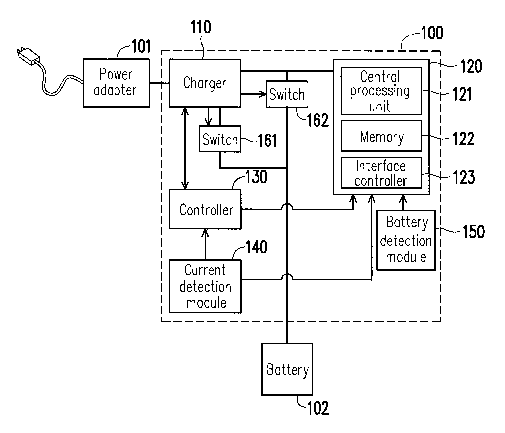
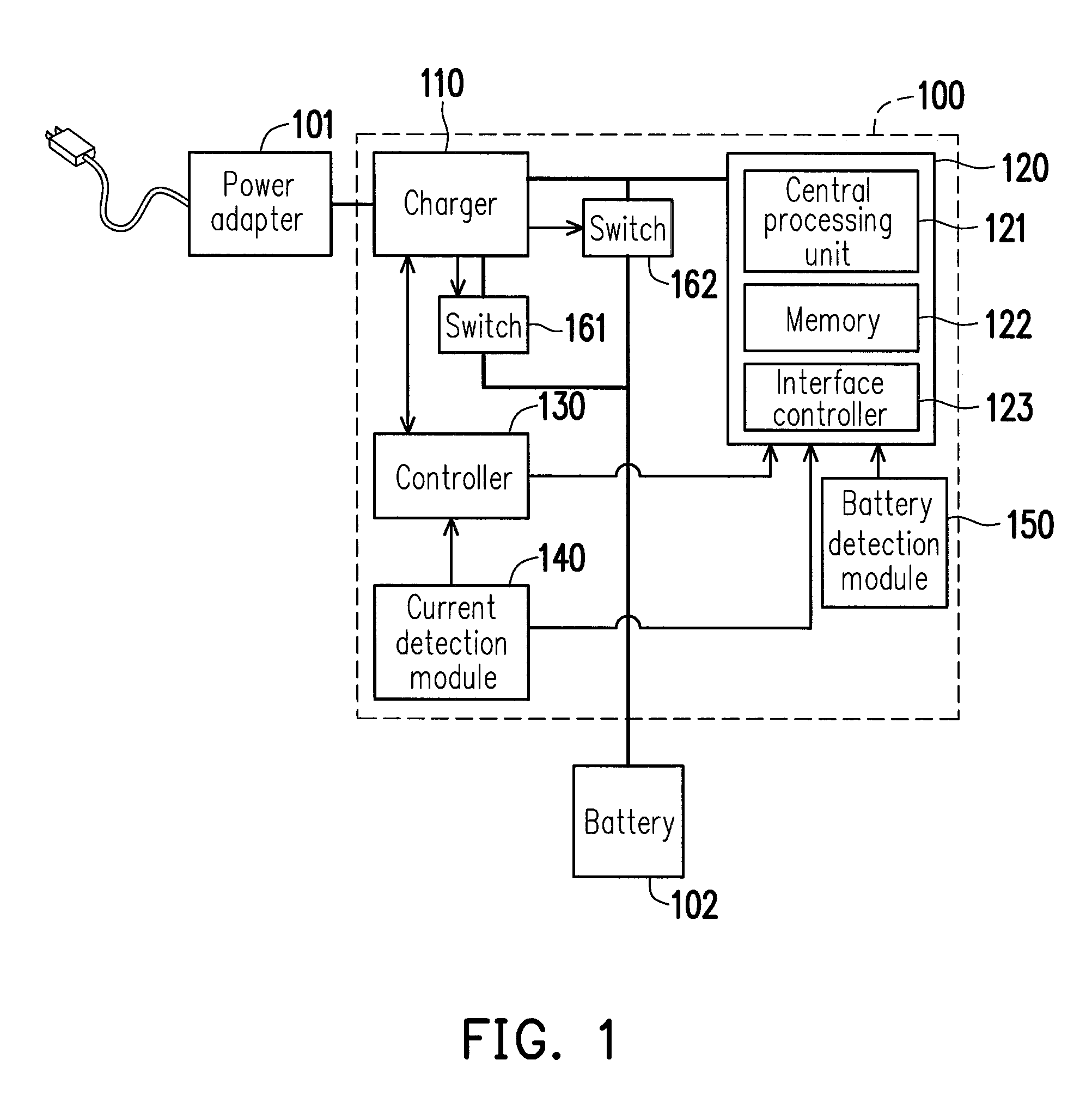
[0020]FIG. 1 is a schematic diagram illustrating an electronic device according to an exemplary embodiment of the present invention. Referring to FIG. 1, an electronic device 100 includes a charger 110, a processor 120, a controller 130, a current detection module 140, a battery detection module 150, a switch 161 and a switch 162. Additionally, the processor 120 includes a central processing unit (CPU) 121, a memory 122 and an interface controller 123. The CPU 121 is mainly responsible for various types of logical operations and program executions. The memory 122 is configured to store various types of data. The interface controller 123 is configured to coordinate input and output of the processor 120. Besides, the controller 130 may be, for example, an embedded controller, and the processor 120 may be, for example, a central processor or a display card processor.
[0021]Moreover, the electronic device 100 may be provided with power through the power adapter 101 and / or the battery 102...
PUM
 Abstract
Description
Claims
Application Information
 - R&D
- Intellectual Property
- Life Sciences
- Materials
- Tech Scout
- Unparalleled Data Quality
- Higher Quality Content
- 60% Fewer Hallucinations
Browse by: Latest US Patents, China's latest patents, Technical Efficacy Thesaurus, Application Domain, Technology Topic, Popular Technical Reports.
© 2025 PatSnap. All rights reserved.Legal|Privacy policy|Modern Slavery Act Transparency Statement|Sitemap|About US| Contact US: help@patsnap.com


