Electric wire with terminal and connector

a technology of electric wire and terminal, which is applied in the direction of cable junctions, connection contact member materials, cable terminations, etc., can solve the problems of oxidation of the surface of the core wire or the wire barrel, water entering the inside and gap left between the one of the ends of the heat-shrinkable tube and the board portion, so as to improve the waterproofness of the electric wire with the terminal

Inactive Publication Date: 2013-05-23
AUTONETWORKS TECH LTD +2
View PDF4 Cites 40 Cited by
  • Summary
  • Abstract
  • Description
  • Claims
  • Application Information

AI Technical Summary

Benefits of technology

[0008]According to the present invention, the outer surface of the water blocking wall provided in the extending portion is in close contact with the inner surface of the water blocking coating. This makes it possible to inhibit the entry of water from between the water blocking wall and the water blocking coating. As a result,

Problems solved by technology

However, in the case of the above-described structure, the board portion has a flat plate shape, and therefore there is a fear that a gap is left between the one of the ends of the heat-shrinkable tube and the board portion.
This may cause a fear th

Method used


Image

  • Electric wire with terminal and connector
  • Electric wire with terminal and connector
  • Electric wire with terminal and connector

Examples


embodiment 1-1

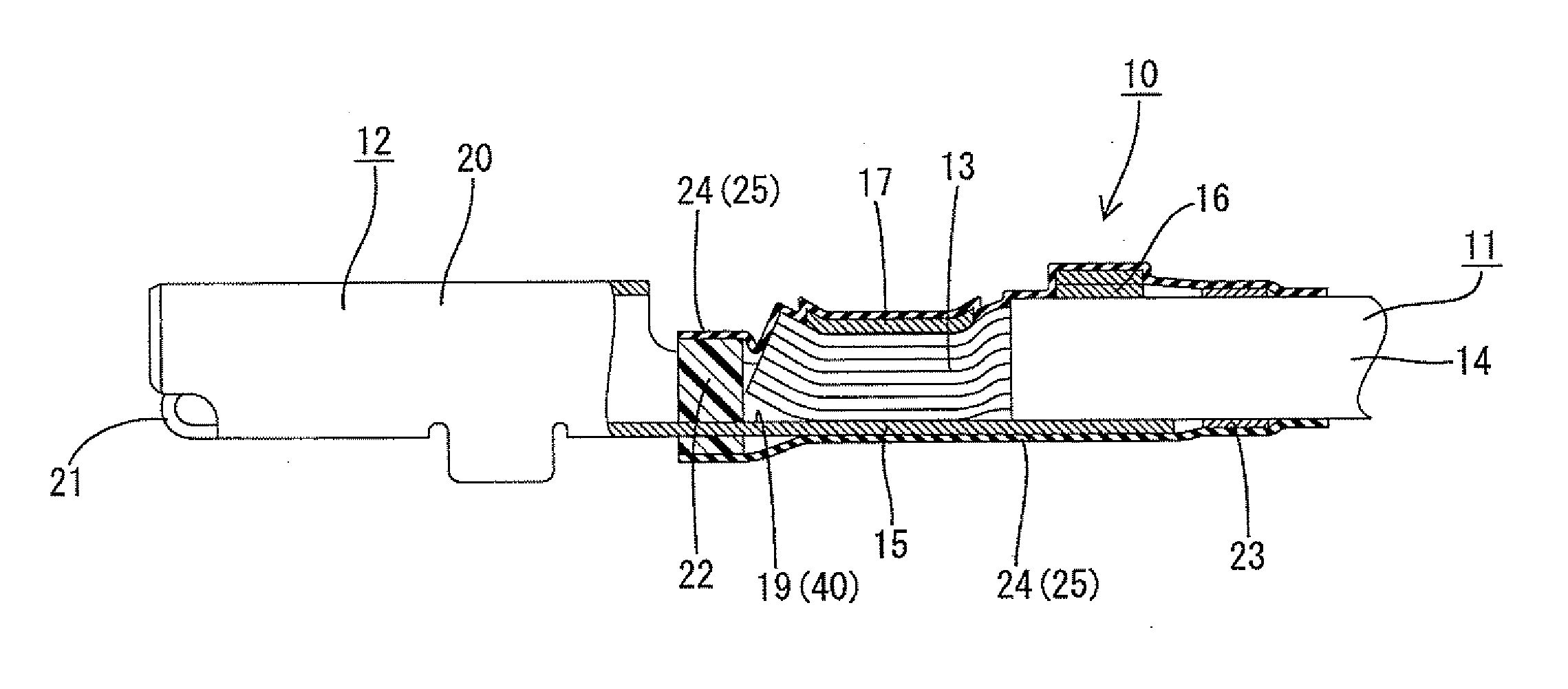
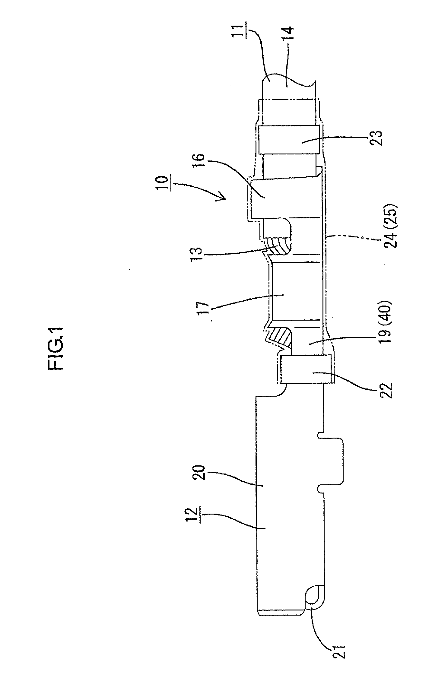
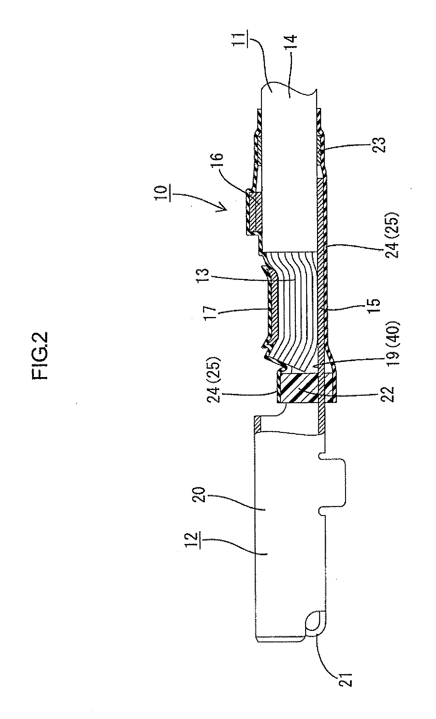
[0225]An electric wire with terminal 10 according to an embodiment 1-1 of the present invention will be described with reference to FIGS. 1 to 5. The electric wire with terminal 10 according to this embodiment is obtained by connecting a female terminal 12 (corresponding to a terminal) to the end of an electric wire 11.

[0226](Electric Wire 11)

[0227]The electric wire 11 includes one core wire 13 obtained by twisting a plurality of thin metallic wires and an insulating coating 14 made of a synthetic resin and covering an outer periphery of the core wire 13. The core wire 13 is made of any metal, such as copper, a copper alloy, aluminum, or an aluminum alloy, as appropriate. In this embodiment, aluminum or an aluminum alloy is used. The insulating coating 14 is stripped off at the end of the electric wire 11 to expose the core wire 13. It is to be noted that the core wire 13 may be a single core wire.

[0228](Female Terminal 12)

[0229]The female terminal 12 is formed by pressing a metalli...

embodiment 1-2

[0269]Hereinbelow, an embodiment 1-2 according to the present invention will be described with reference to FIG. 6. In this embodiment, the water blocking wall 22 is provided so as to fill the inside of the groove portion 19, but the outer periphery of the groove portion 19 is not covered with the water blocking wall 22. Further, the water blocking wall 22 is provided so as to bulge out over the upper edges of sides of the groove portion 19. The inner surface of the heat-shrinkable tube 24 is in close contact with the water blocking wall 22 without any gap and is also in close contact with the outer periphery of the groove portion 19 without any gap. The structure of this embodiment is substantially the same as that of the embodiment 1-1 except for the above-described point, and the same members as the embodiment 1-1 are denoted by the same reference numerals and a description thereof will not be repeated.

[0270]According to this embodiment, the water blocking wall 22 is provided so ...

embodiment 1-3

[0272]Hereinbelow, an embodiment 1-3 according to the present invention will be described with reference to FIG. 7. In this embodiment, the resin ring 23 is omitted. The heat-shrinkable tube 24 covers a region extending from part of the groove portion 19 where the water blocking wall 22 is provided to the end of the insulating coating 14 through the wire barrels 17 and the insulation barrels 16. The inner surface of the heat-shrinkable tube 24 is in close contact with the outer surface of the insulating coating 14. The structure of this embodiment is substantially the same as that of the embodiment 1-1 except for the above-described point, and the same members as the embodiment 1-1 are denoted by the same reference numerals and a description thereof will not be repeated.

[0273]According to this embodiment, the region extending from part of the groove portion 19 where the water blocking wall 22 is provided to the end of the insulating coating 14 through the wire barrels 17 and the ins...


PUM


Abstract

An electric wire with terminal includes an electric wire covering an outer periphery of a core wire with an insulating coating and a female terminal. The female terminal includes: a wire barrel having a bottom plate on which the core wire is placed and crimped onto the core wire; a groove portion extending from the bottom plate in a direction in which the core wire extends and whose surface on the side where the core wire is placed is bent into a concave shape. The groove portion has a water blocking wall molded by synthetic resin. The water blocking wall is provided to fill the inside of the groove portion. A region extending from the water blocking wall to the end of the insulating coating is covered with a water blocking coating, and the inner surface of the water blocking coating is in close contact with the water blocking wall.

Description

TECHNICAL FIELD[0001]The present invention relates to an electric wire with terminal and a connector.BACKGROUND ART[0002]As a conventional electric wire with terminal, one disclosed in Patent Document 1 is known. This electric wire with terminal includes: an electric wire covering the outer periphery of a core wire with an insulating coating; and a terminal connected to an exposed portion of the core wire not covered with the insulating coating. The terminal has a flat plate-shaped board portion on which the core wire is placed and a wire barrel that projects from the board portion and is crimped onto the core wire.[0003]A region extending from the board portion to the end of the insulating coating is covered with a heat-shrinkable tube. One of the ends of the heat-shrinkable tube covers the core wire onto which the wire barrel is crimped and the other end is in close contact with the insulating coating.Patent Document[0004]Patent Document 1: JP 2000-285983 ADISCLOSURE OF THE INVENT...

Claims


Application Information

Patent Timeline
IPC IPC(8): H02G15/08
CPCH02G15/08H01R4/185H02G15/046H01R4/70H01R4/62H01R4/186H01R4/188H01R4/72
Inventor ONO, JUNICHISAIJO, EIJIHIRAI, HIROKIOTSUKA, TAKUJISHIMODA, HIROKIKAWASE, HAJIMEINOUE, TAKUYATABATA, MASAAKINAKATA, TAKEHIROMORIKAWA, SATOSHIKOSAKA, MIKIKO
Owner AUTONETWORKS TECH LTD
Why Eureka
Try Eureka