Control System For A Boiler Assembly

a control system and boiler technology, applied in the field of boilers or heaters, can solve the problems of back pressure generated by the boiler assembly and ignition blowout, and achieve the effects of facilitating the ignition process of the second boiler unit, reducing the blower speed range, and reducing the occurrence of ignition blowou

Active Publication Date: 2013-05-23
LOCHINVAR
View PDF4 Cites 10 Cited by
  • Summary
  • Abstract
  • Description
  • Claims
  • Application Information

AI Technical Summary

Benefits of technology

[0009]The control system of the present invention allows the first boiler control unit to modulate the output of the first boiler unit in response to the input heat demand. Moreover, if the input heat demand exceeds the first boiler unit's capacity, the first control unit may direct the second boiler unit to fire. Once both the first and second boilers have fired, the first boiler control unit modulates the first and second boiler units to satisfy the input heat demand while maintaining comparable outputs between the two boiler units.
[0010]One problem associated with the firing of the second boiler unit, as described above, involves ignition blowout. Consider that when the control system of the present invention determines that the second boiler unit must be called into service, because the input heat demand exceeds the maximum output of the first boiler unit, the blower assembly of the first boiler unit is operating near its threshold. The back pressure generated by the blower assembly poses an obstacle to successfully firing the second boiler assembly because the two boilers are connected to a common flue. To minimize the occurrence of ignition blowout of the second boiler unit, the present invention, via the first boiler control unit, causes the blower assembly of the first boiler unit to operate in a reduced blower speed range. Operating the blower assembly in this range facilitates the ignition process of the second boiler unit. After the second boiler has been fired, the boiler unit(s) may resume normal operation.
[0013]The interface control system is also capable of communicating with the third and fourth boiler control units, via the first boiler control unit, to report the operating parameters of the third and fourth boiler units, in addition to the first and second units, to the interface. Thus, the interface control system and the interface work to provide a central mechanism from which the boiler assembly can be monitored and operated. In this way the control system of the present invention serves to manage and interface multiple boiler systems having multiple boiler units arranged in a cascade configuration.

Problems solved by technology

One problem associated with the firing of the second boiler unit, as described above, involves ignition blowout.
The back pressure generated by the blower assembly poses an obstacle to successfully firing the second boiler assembly because the two boilers are connected to a common flue.

Method used


Image

  • Control System For A Boiler Assembly
  • Control System For A Boiler Assembly
  • Control System For A Boiler Assembly

Examples


Embodiment Construction

[0030]The control system of the present invention operates on water heaters or boilers. As used herein, the term water heater refers to a device for heating water, including water heaters that do not actually “boil” the water. Much of this discussion refers to a boiler, but it will be understood that this description is equally applicable to water heaters that do not boil the water.

Boiler Assembly Structure / Arrangement

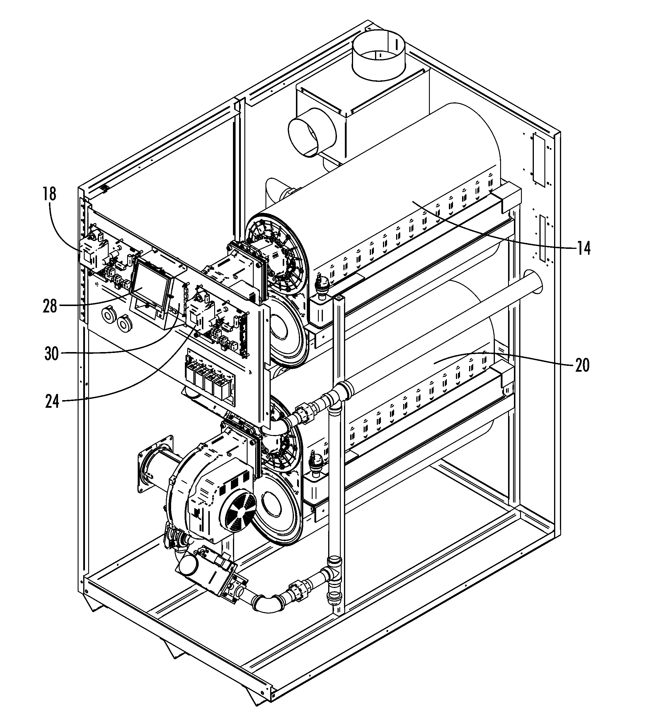
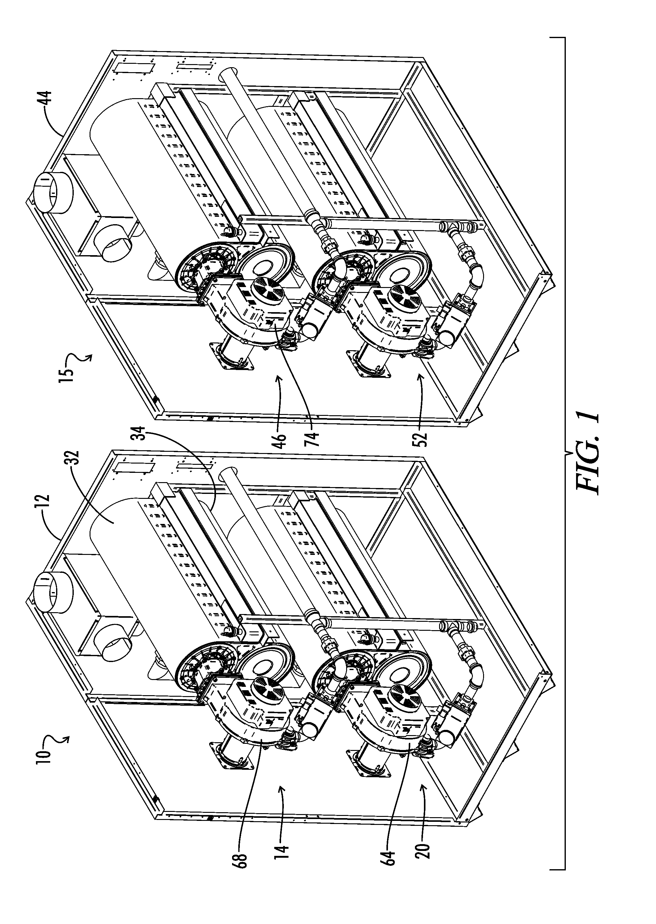
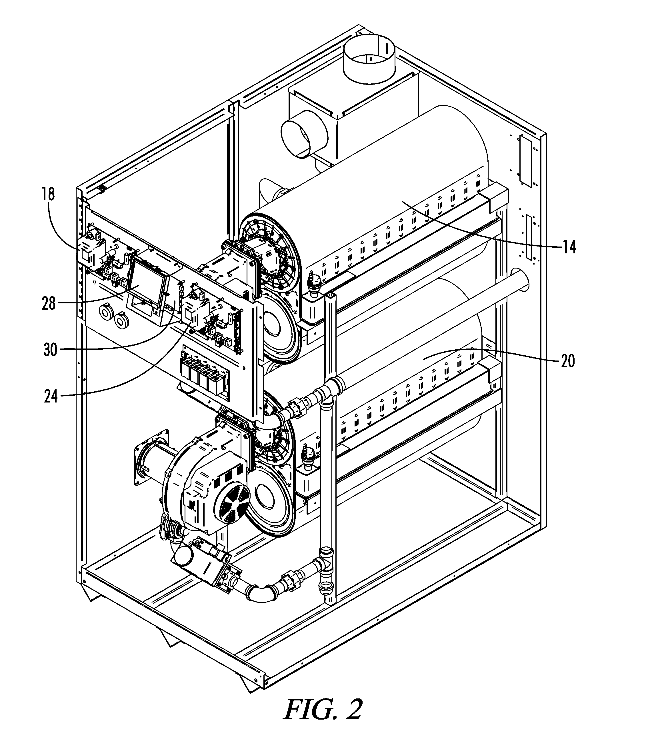
[0031]Now referring to the figures, FIG. 1 shows a boiler system, a boiler system can be described as an apparatus that has at least two boiler units contained in a common boiler housing. Specifically, FIG. 1 depicts a first boiler system 10 with a first boiler unit 14 and a second boiler unit 20 located in a first boiler housing 12. FIG. 9 shows an exemplary embodiment of the first boiler unit 14, more specifically a partially disassembled first boiler unit 14. The basic architecture of the exemplary embodiment of the first boiler unit 14 includes: a primary heat exch...


PUM


Abstract

A control system for managing and interfacing a plurality of water heaters, e.g. boilers. The control system includes a first boiler unit controlled by a first boiler control unit and a second boiler unit controlled by a second boiler control unit. The first boiler control unit is operable to coordinate the operation of the first and second boiler units in response to changes in output demand. The flues of the first and second boiler units are connected to a common flue. The control system further includes an interface and an interface control system. The interface control system communicates requests from the interface, to report and / or alter the operating parameters of the first and second boiler units, to the first and second boiler control units and communicates the request outcome(s) back to the interface.

Description

BACKGROUND OF THE INVENTION[0001]1. Field of the Invention[0002]The present invention relates generally to boilers or heaters for heating water, and more particularly, but not by way of limitation, to a control system for managing and interfacing a plurality of boilers.[0003]2. Description of the Prior Art[0004]To service facilities having significant demand for heat input into the water supply system, it is well-known in the prior art to employ multiple water heating units, working with coordinated efforts, to satisfy the demand. One such prior art water heating system is based on the KNIGHT™ XL, which has been marketed by Lochinvar Corporation, the assignee of the present invention. The KNIGHT XL features SMART SYSTEM™, which coordinates the operation of a group of individual KNIGHT XL water heating units so that the individual units may function, in concert, to supply heat input into a water supply system.[0005]Specifically, the SMART SYSTEM includes a cascading sequencer. SMART ...

Claims


Application Information

Patent Timeline
Patent Type & Authority Applications(United States)
IPC IPC(8): F24H9/20
CPCF24H9/2035F22B37/06F22B35/008F22B33/00F24H15/20F24H15/35F24H15/281F24H15/414F24H15/36F24H15/174F24H15/395F24H9/28
Inventor PAINE, JOHN C.
Owner LOCHINVAR
Why Eureka
Try Eureka