
Conductor and rotating electrical machine

a technology of rotating electrical machines and conductors, which is applied in the direction of flexible cables, flexible conductors, windings, etc., can solve the problems of reducing the slot or the tooth cannot necessarily have an optimal shape, and the reduction of the diameter of the conductor wire, etc., to achieve the effect of simplifying the process of winding the conductor and increasing the ratio of the area occupied by the coil

Active Publication Date: 2013-05-23
AISIN AW CO LTD
View PDF3 Cites 16 Cited by
  • Summary
  • Abstract
  • Description
  • Claims
  • Application Information

AI Technical Summary

Benefits of technology

This patent is about a new type of conductor that can make it easier to wind a coil around a core and increase the amount of space occupied by the coil, regardless of the materials used or the shape of the slot. The technical effects are greater efficiency and flexibility in coil winding.

Problems solved by technology

As described above, in the conductor formed by using the conductor wires having a circular cross section, a gap tends to be formed between the conductor wires in each slot when the conductor is attached to the stator, and it is difficult to increase the ratio of the area occupied by the coil.
However, reducing the diameter of the conductor wires has problems.
However, the slot shape is also limited to a substantially rectangular shape corresponding to the cross-sectional shape of the conductor wires, and the slots or teeth can not necessarily have an optimal shape.

Method used


Image

  • Conductor and rotating electrical machine
  • Conductor and rotating electrical machine
  • Conductor and rotating electrical machine

Examples


Embodiment Construction

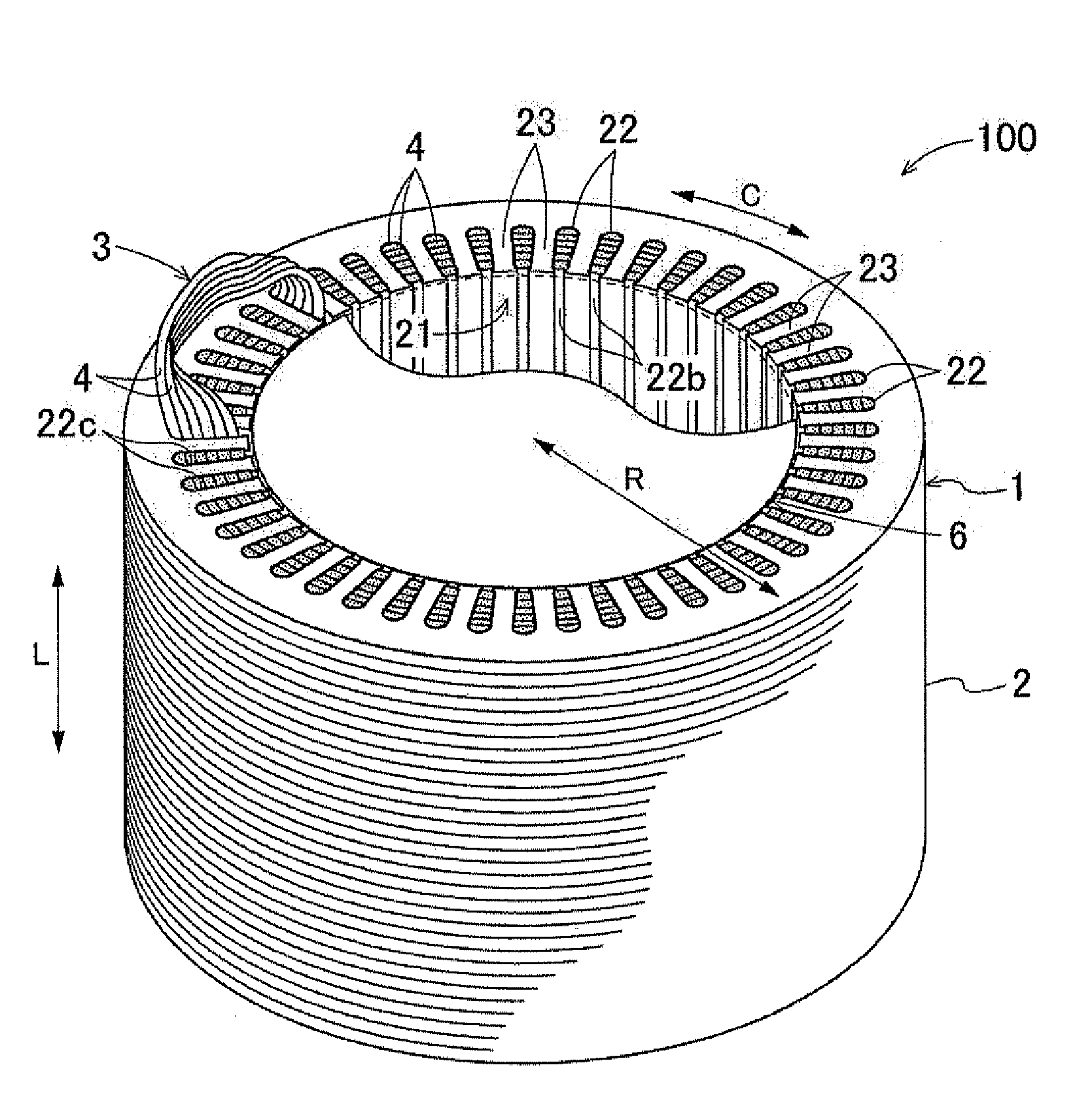
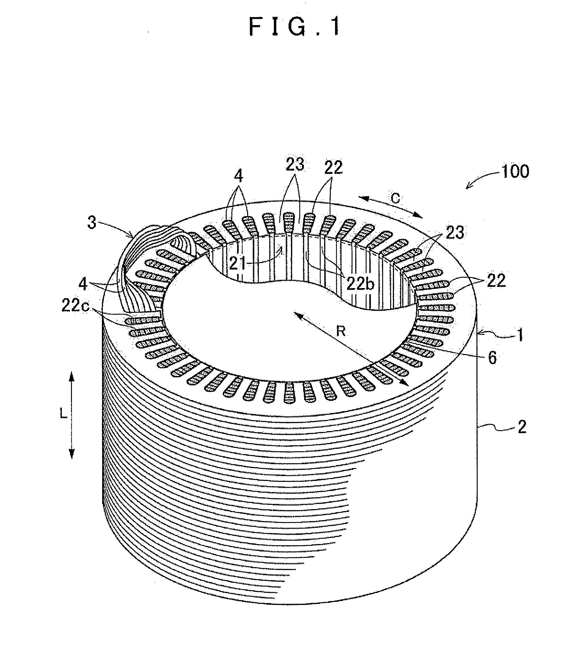
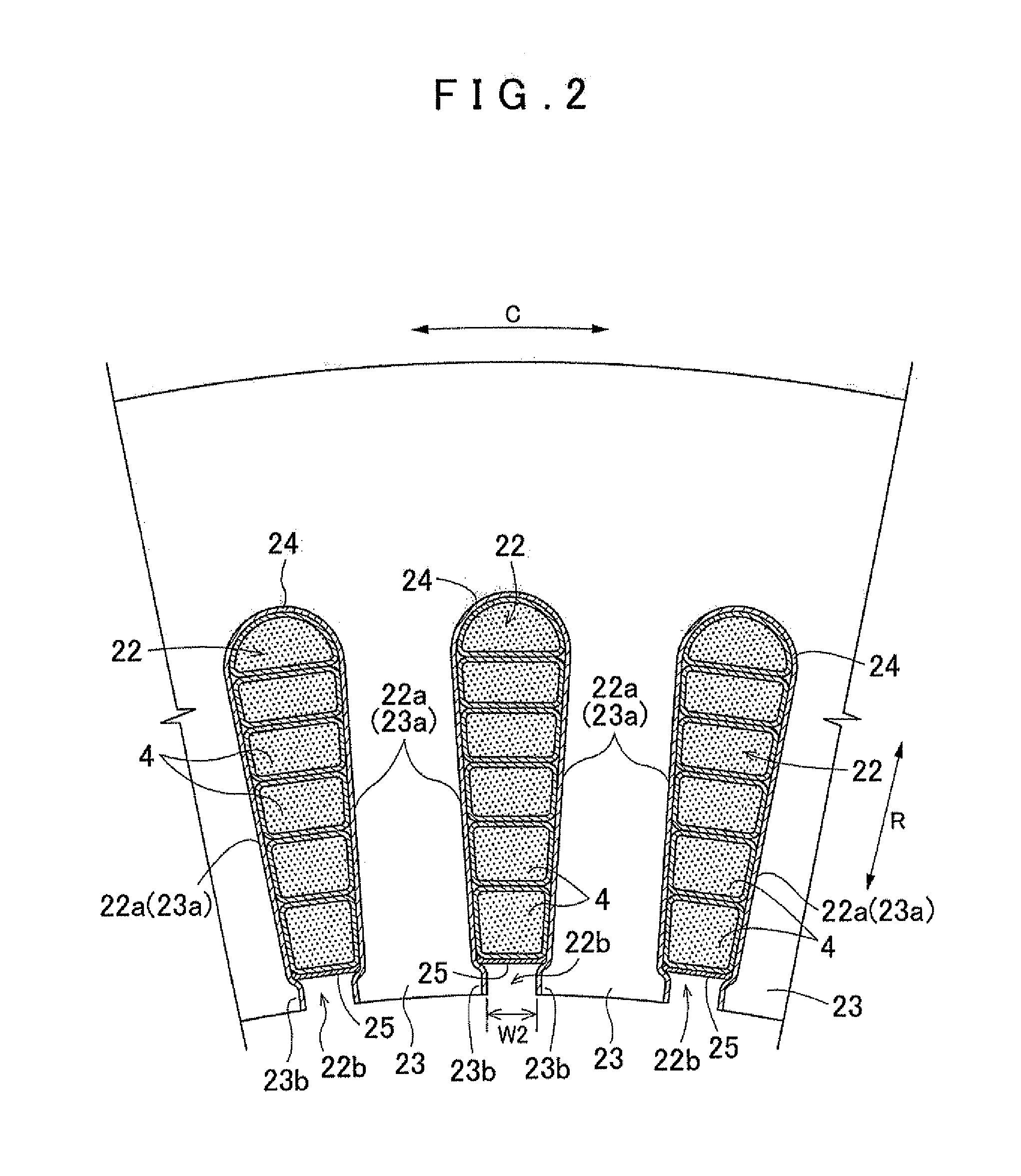
[0039]An embodiment of a conductor and a rotating electrical machine including the conductor according to the present invention will be described below with reference to the accompanying drawings. An example will be described below in which the conductor according to the present invention is applied to a coil 3 of an inner rotor rotating electrical machine 100. As shown in FIG. 3, a conductor 4 for the coil 3 includes a conductor wire bundle 42 formed by gathering a plurality of conductor wires 41, and a flexible insulating covering material 46 covering the periphery of the conductor wire bundle 42. That is, the conductor 4 is structured so that the periphery of the conductor wire bundle 42 formed by gathering the plurality of conductor wires 41 is covered by the flexible insulating covering material 46. The conductor 4 according to the present embodiment is characterized by its inner structure, and the rotating electrical machine 100 is characterized by using such a conductor 4. Th...


PUM


Abstract

A conductor for a coil of a rotating electrical machine that includes a conductor wire bundle formed by gathering a plurality of conductor wires and a flexible insulating covering material that covers a periphery of the conductor wire bundle. The conductor has an intra-covering gap formed inward of the insulating covering material in a radial direction so that the conductor wires can move relative to each other in the intra-covering gap, and a cross-sectional shape of the insulating covering material along a perpendicular plane that is perpendicular to an extending direction in which the conductor wire bundle extends can be deformed.

Description

INCORPORATION BY REFERENCE[0001]The disclosure of Japanese Patent Application No. 2011-254147 filed on Nov. 21, 2011 including the specification, drawings and abstract is incorporated herein by reference in its entirety.BACKGROUND OF THE INVENTION[0002]The present invention relates to conductors for coils of rotating electrical machines, and rotating electrical machines including the conductors.DESCRIPTION OF THE RELATED ART[0003]A stator included in a rotating electrical machine as an electric motor or an electric generator is formed by attaching a coil to a stator core having a plurality of slots. A rotor included in the rotating electrical machine can similarly be formed by attaching a coil to a rotor core having a plurality of slots. For example, Japanese Patent Application Publication No. H09-009588 (JP H09-009588 A) describes a stator including a coil formed by winding conductor wires having a circular cross section many times in a plurality of slots distributed in the circumf...

Claims


Application Information

Patent Timeline
IPC IPC(8): H02K3/34H01B7/04
CPCH02K3/12H02K3/34H01F5/06H01F5/00
Inventor KOGA, KIYOTAKA
Owner AISIN AW CO LTD
Learn More