Stenciled Layer Peeling Graphics Processing

a technology of graphics processing and peeling layers, applied in the field of computer systems, can solve the problems of hidden surface removal, increased complexity of personal computer systems, and increased complexity of graphics operations and graphical data

Active Publication Date: 2013-05-23
ADOBE INC
View PDF4 Cites 5 Cited by
  • Summary
  • Abstract
  • Description
  • Claims
  • Application Information

AI Technical Summary

Benefits of technology

[0015]Various embodiments of systems, methods, and computer-readable storage media for rendering artwork including semi-transparent surfaces are disclosed. A three-dimensional computer graphics artwork may comprise a plurality of surfaces including a plurality of semi-transparent surfaces and optionally one or more opaque surfaces. The semi-transparent surfaces may be unsorted relative to their depth order prior to rendering. According to one embodiment, an identifier of the nearest semi-transparent surface may be determined and stored in a stencil count of a stencil buffer. The identifier may comprise the number of surfaces encountered after the nearest semi-transparent surface in the draw order or the number of surfaces encountered before the nearest semi-transparent surface in the draw order.
[0016]The depth of the second nearest semi-transparent surface may be determined using a stencil test based on the stencil count to bypass the nearest semi-transparent surface. The second nearest semi-transparent surface may be rendered to an image buffer. According to one embodiment, a z-equals test based on the determined depth of the second nearest semi-transparent surface may be used in rendering the second nearest semi-transparent surface. The nearest semi-transparent surface may then be rendered to the image buffer. According to one embodiment, a z-less test based on the determined depth of the second nearest semi-transparent surface may be used in rendering the nearest semi-transparent surface.
[0017]A nearest opaque surface in the artwork may be rendered prior to rendering the semi-transparent surfaces. According to one embodiment, the surfaces may be rendered using full-screen anti-aliasing by rendering the surfaces to a multi-sampling buffer at a multi-sampled resolution and then reducing the rendered surfaces from the multi-sampled resolution to a display resolution.

Problems solved by technology

As the power and complexity of personal computer systems increase, graphics operations and graphical data are likewise increasing in complexity.
A typical problem encountered when rendering 3-D artwork is hidden surface removal, which involves finding the nearest surface at each pixel.
However, this technique may be inefficient for complex models containing intersecting surfaces, e.g., where the triangles that make up a surface are broken up into smaller pieces.
When using the Z-buffer technique to render images, however, aliasing artifacts may result on edges of the geometry.
Pixel shaders may be relatively expensive to execute.
A drawback of the layer peeling technique is the need for a second Z-buffer: for example, a first Z-buffer (i.e., an opaque-z-buffer or visibility-z-buffer) may be used to store the depth of the nearest opaque surface, and a second Z-buffer (i.e., a cull-z-buffer) may be used for rendering transparent geometry for each iteration, with the nearest opaque surface color being blended in the end.
Conventional approaches towards layer peeling, however, are currently incompatible with full-screen anti-aliasing.
If full-screen anti-aliasing is not disabled when conventional layer peeling is employed, errors in rendering may result from inexact matches between the cull-z-buffer and the visibility-z-buffer.
For similar reasons, extensions such as coherent layer peeling and dual layer peeling may also be incompatible with full-screen anti-aliasing.

Method used


Image

  • Stenciled Layer Peeling Graphics Processing
  • Stenciled Layer Peeling Graphics Processing
  • Stenciled Layer Peeling Graphics Processing

Examples


Embodiment Construction

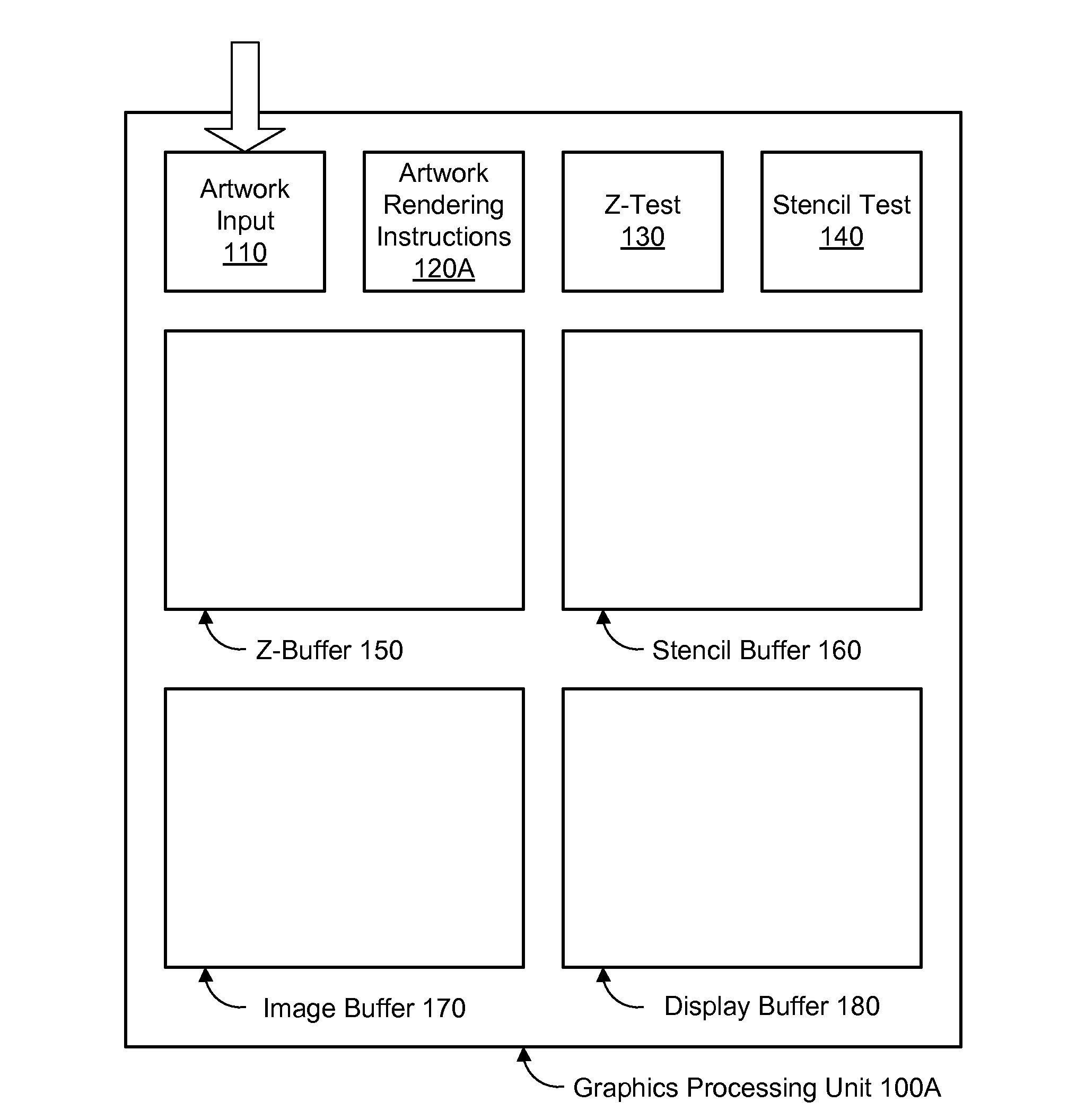
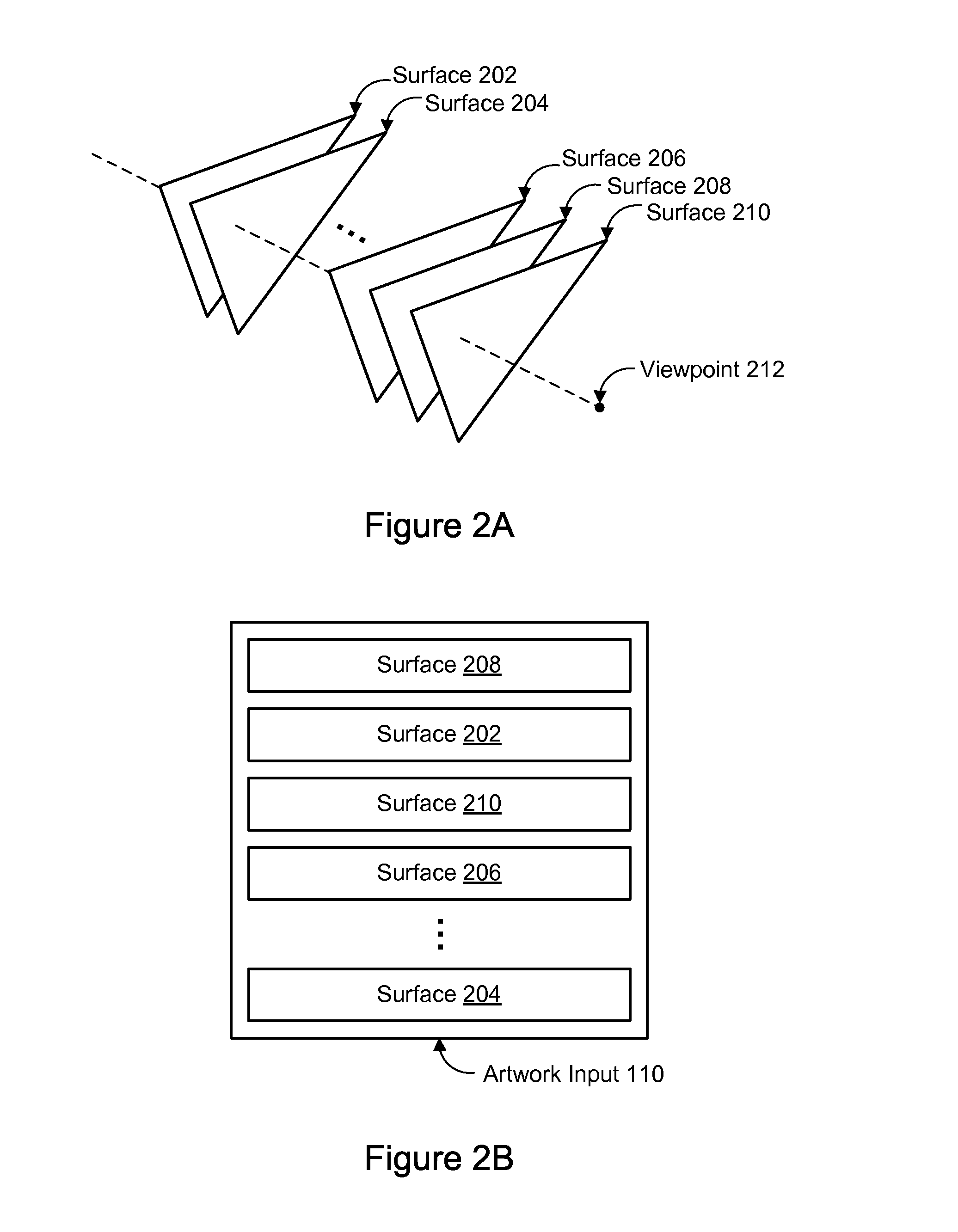
[0029]Using embodiments of the systems and methods described herein, an instance of computer graphics artwork (referred to herein as “an artwork”) comprising a plurality of semi-transparent surfaces may be partially rendered in an efficient manner using Stenciled Layer Peeling techniques. Stenciled Layer Peeling may be used to render the two nearest semi-transparent surfaces along with the nearest opaque surface. In one embodiment, full-screen anti-aliasing (e.g., using multi-sampling hardware) may be used during the rendering of surfaces with Stenciled Layer Peeling.

[0030]In the following detailed description, numerous specific details are set forth to provide a thorough understanding of claimed subject matter. However, it will be understood by a person of ordinary skill in the art in light of this specification that claimed subject matter may be practiced without necessarily being limited to these specific details. In some instances, methods, apparatuses or systems that would be k...


PUM


Abstract

A method, system, and computer-readable storage medium are disclosed for rendering an artwork comprising a plurality of surfaces, wherein the plurality of surfaces comprises a plurality of semi-transparent surfaces unsorted in depth. An identifier of the nearest semi-transparent surface may be determined and stored in a stencil count of a stencil buffer. The depth of the second nearest semi-transparent surface may be determined using a stencil test based on the stencil count to bypass the nearest semi-transparent surface. The second nearest semi-transparent surface may be rendered to an image buffer, and the nearest semi-transparent surface may be rendered to the image buffer.

Description

BACKGROUND[0001]1. Field of the Invention[0002]The present invention is directed to computer systems; and more particularly, it is directed to rendering artwork including semi-transparent surfaces using computer systems.[0003]2. Description of the Related Art[0004]As the power and complexity of personal computer systems increase, graphics operations and graphical data are likewise increasing in complexity. For example, an instance of three-dimensional (3-D) artwork may include numerous layers of graphical data. The layers may be related in complex ways based on their relative depth as well as their transparency properties. The layers may also be referred to as surfaces. It is desirable to render artwork containing such layers (e.g., for display on a display device) both correctly and efficiently.[0005]A typical problem encountered when rendering 3-D artwork is hidden surface removal, which involves finding the nearest surface at each pixel. Because the image is created using only th...

Claims


Application Information

Patent Timeline
Patent Type & Authority Applications(United States)
IPC IPC(8): G06T15/40
CPCG06T15/405G06T2210/62G06T2200/28G06T11/40
Inventor MILLER, GAVIN S. P.KIM, BYUNGMOONLANG, GRAYSON SQUIER
Owner ADOBE INC
Why Eureka
Try Eureka