Method and system for detecting object on a road

a technology of object detection and method, applied in the field of method and system for detecting objects on the road, can solve the problems of increasing the number of injuries, increasing the number of accidents, and dramatic loss of personal property, and achieves the effect of increasing the processing speed of the method and system and increasing the detection accuracy

Active Publication Date: 2013-05-23
RICOH KK
View PDF3 Cites 40 Cited by
  • Summary
  • Abstract
  • Description
  • Claims
  • Application Information

AI Technical Summary

Benefits of technology

[0021]According to the above described method and system, it is possible to achieve a processing speed of 17 frames per second; as a result, the processing speed in the method and system is greater than those of the conventional techniques. Furthermore, in the method and system, a V-disparity image is adopted for seeking an object sub-disparity map including an object, and then th

Problems solved by technology

With the development of cities and the popularization of vehicles, the problem of traffic and transportation has become bigger.
In the meanwhile, traffic accidents occur frequently, the number of injuries has increased, and personal property has been lost dramatically.
Since the grouping process is conducted on the whole disparity map, and only two frames of results are able to be obtained in one second, the method takes time, and diminishes the efficiency of dealing with an unforeseen accident.
Since the mean shift clustering process is utilized to divide an image, and the U-

Method used


Image

  • Method and system for detecting object on a road
  • Method and system for detecting object on a road
  • Method and system for detecting object on a road

Examples


Embodiment Construction

[0037]The aim of the present invention is to provide a method and a system for detecting at least one object on a road, to enable to be helpful to achieve safe driving.

[0038]Hereinafter, embodiments of the present invention will be concretely described with reference to the drawings. However it should be noted that the same symbols, which are in the specification and the drawings, stand for constructional elements having basically the same function and structure, and repeated explanations for the constructional elements are omitted.

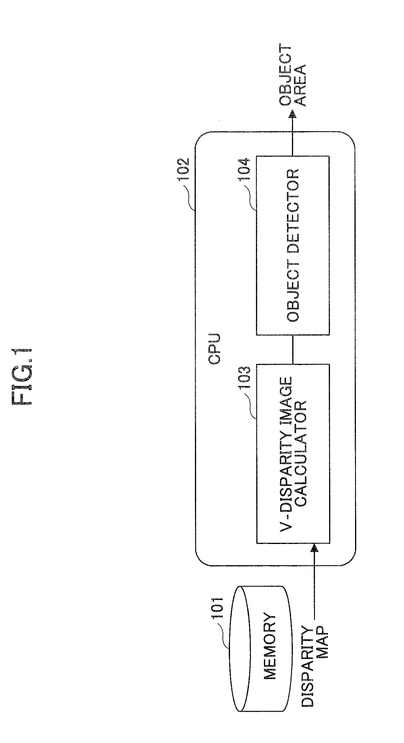
[0039]FIG. 1 is a basic block diagram of a system according to an embodiment of the present invention; the system adopts a method of detecting at least one object on a road.

[0040]As shown in FIG. 1, the method is fulfilled basically in a CPU 102; of course, it may also be achieved among plural modules independent of each other or connected to each other. The system in this embodiment comprises a memory 101 and the CPU 102. The CPU 102 includes a V-dispari...


PUM


Abstract

Disclosed are a method and a system for detecting an object on a road. The method comprises a step of simultaneously capturing two depth maps, and then calculating a disparity map; a step of obtaining, based on the disparity map, a V-disparity image by adopting a V-disparity algorithm; a step of detecting an oblique line in the V-disparity image, and then removing points in the disparity map, corresponding to the oblique line so as to acquire a sub-disparity map excluding the road; a step of detecting plural vertical lines in the V-disparity image, and then extracting, for each of the plural vertical lines, points corresponding to this vertical line from the sub-disparity map as an object sub-disparity map corresponding to this vertical line; and a step of merging any two rectangular areas of the object sub-disparity maps approaching each other, into a rectangular object area.

Description

BACKGROUND OF THE INVENTION[0001]1. Field of the Invention[0002]The present invention relates to a method and a system for detecting at least one object on a road, more particularly relates to a method and a system used in a vehicle for detecting at least one object on a road.[0003]2. Description of the Related Art[0004]With the development of cities and the popularization of vehicles, the problem of traffic and transportation has become bigger. In recent years, the speed of increase of vehicles has been far higher than that of roads and other traffic facilities. In the meanwhile, traffic accidents occur frequently, the number of injuries has increased, and personal property has been lost dramatically. As a result, a vehicle was required to have not only good safety but also a certain degree of intelligence. In the light of this, the intelligent vehicle concept occurred. At present, research is being performed for achieving an intelligent vehicle able to carry out unattended, fully-...

Claims


Application Information

Patent Timeline
IPC IPC(8): H04N7/18H04N13/02
CPCG06K9/00208G06K9/00798G06T7/0042H04N7/18H04N13/0203G06K9/00805G06T2207/10028G06T2207/30261G06T7/75G06V20/647G06V20/588G06V20/58H04N13/204
Inventor YOU, GANMEILU, YAOJIEZHENG, JICHUAN
Owner RICOH KK
Why Eureka
Try Eureka