
Apparatus for vertically segmenting a boiling water reactor control rod blade

Active Publication Date: 2013-05-23
WESTINGHOSE ELECTRIC CORP
View PDF5 Cites 4 Cited by
  • Summary
  • Abstract
  • Description
  • Claims
  • Application Information

AI Technical Summary

Benefits of technology

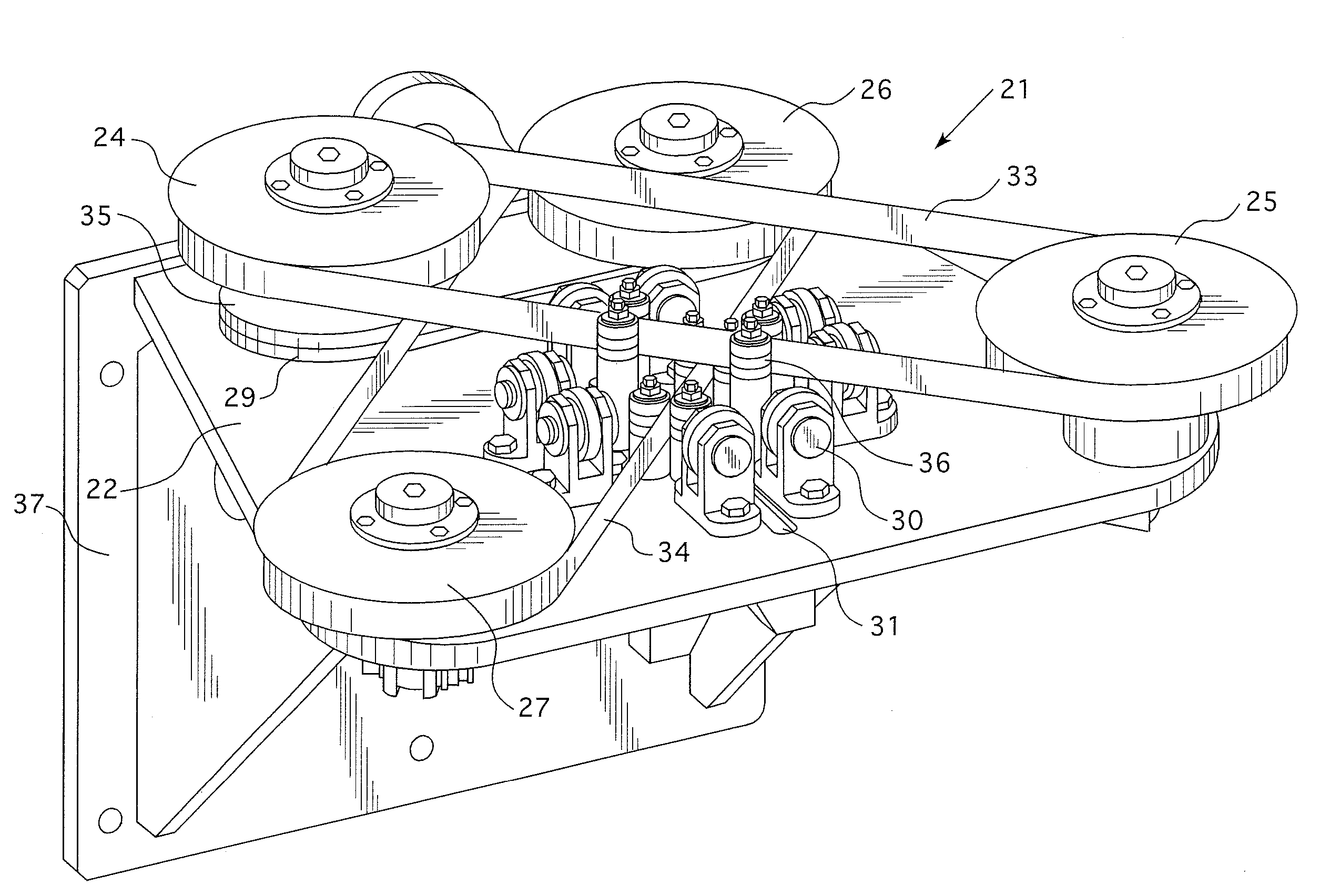
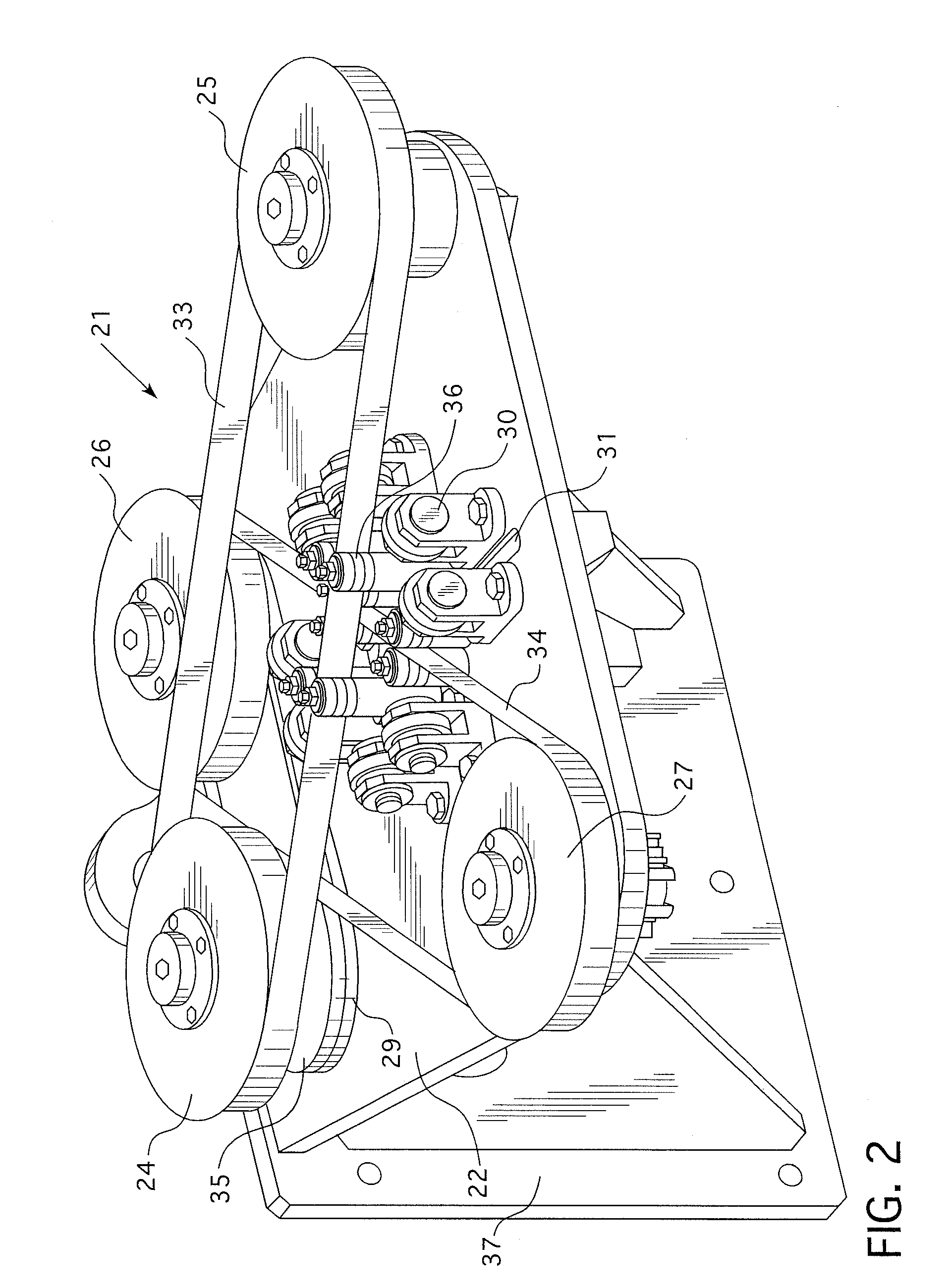
The patent describes an apparatus for reducing the storage volume of a boiling water reactor control rod by cutting the spline along its central axis into four sections using a double bladed band saw. The apparatus includes a tool base plate with guides for positioning the control rod panels, a chain and sprocket coupling for driving the band saw blades, and a camera for observing and managing the cutting process. The technical effect of the invention is to reduce the space required for storing the control rod and facilitate maintenance of the reactor.

Problems solved by technology

Following functional service, boiling water reactor control rod blades are difficult to store and dispose of because of their size, configuration, embrittled condition, and radiological activity.
Heretofore within the United States, in-pool storage of control rod blades has been extremely space inefficient and dry cask storage is not readily available.
The control rod design may vary with the manufacturer, but the four-panel design with the panels radially extending from a central spline at 90° intervals around the circumference of the control rod is common to all of the boiling water reactor designs, and thus, a common storage problem.
Lack of disposal capacity has caused boiling water reactor operators considerable spent fuel pool overcrowding.
This type of process requires three approximately 4 meter long cuts with handling time in between that makes this an arduous process.
The packing of the segmented blades is also inefficient leading to high customer costs.
Each of the approaches yields 12-foot (3.6 meters) or longer segments that are costly to shield and transport.
Thus, horizontal segmentation of the blades, which would cut across the sealed rods that contain the neutron absorber material and the radioactive gases, while making the handling of the blades more manageable, is problematic.

Method used


Image

  • Apparatus for vertically segmenting a boiling water reactor control rod blade
  • Apparatus for vertically segmenting a boiling water reactor control rod blade
  • Apparatus for vertically segmenting a boiling water reactor control rod blade

Examples


Embodiment Construction

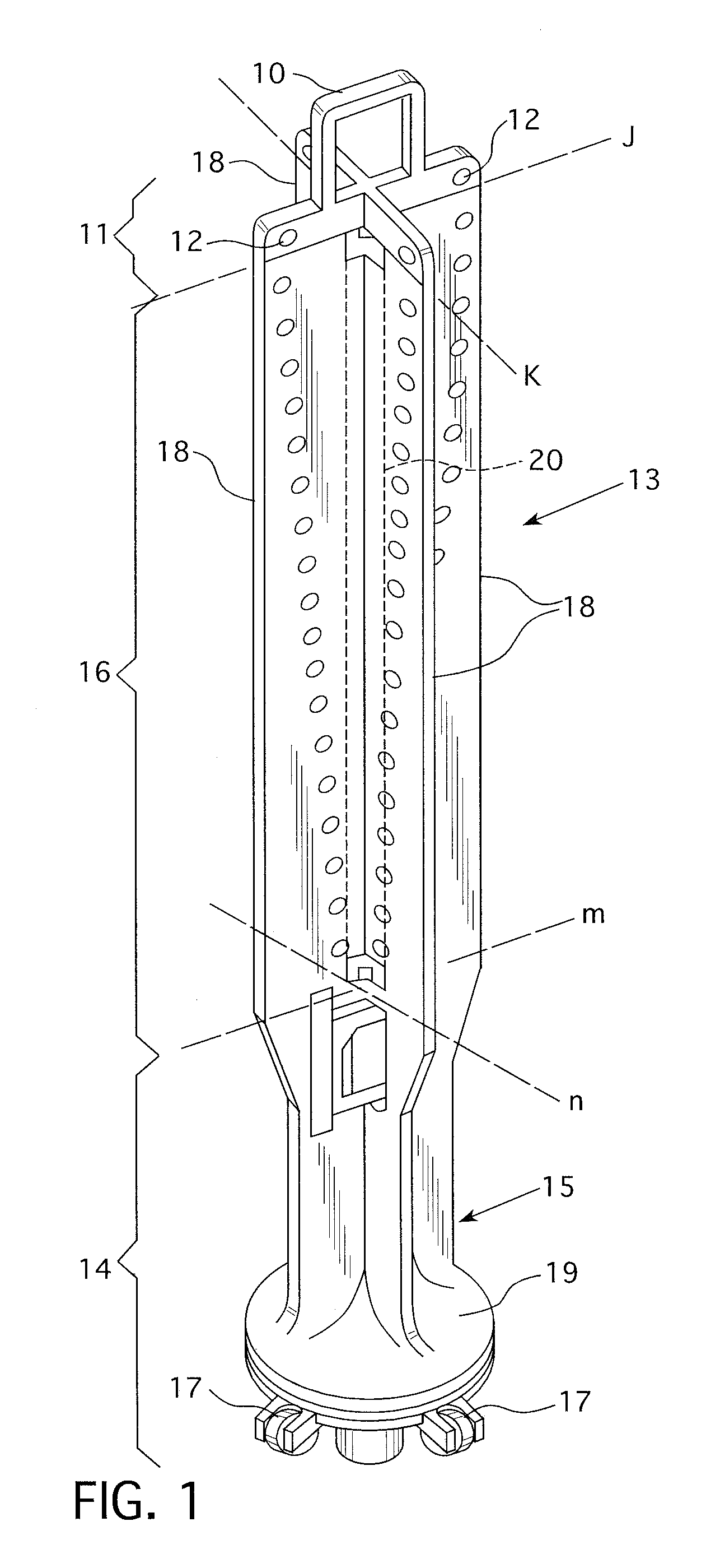
[0027]FIG. 1 shows a boiling water reactor control rod blade 13 of the type to which the present invention is applicable. As such, the control rod blade comprises an upper portion 11 having an upper handle 10 and four upper ball rollers 12; a lower portion 14 having a lower casting 15 and lower ball rollers 17; and a main blade structure 16 therebetween. The main blade structure 16 includes four panels or blades 18 arranged in a cruciform shape about a central spline 20. According to one embodiment of the invention, the lower portion 14 is removed by cutting approximately in the plane defined by lines m and n, and the upper portion 11 is removed by cutting in a transverse plane defined by lines j and k. Another alternative is to just cut around the rollers to remove them or to leave the handle 10 in place. Although it is possible to practice the invention without removing the rollers, it is desirable to do so since they typically contain cobalt and from a radiological perspective, a...


PUM

PropertyMeasurementUnit
Lengthaaaaaaaaaa
Angleaaaaaaaaaa
Angleaaaaaaaaaa

Abstract

Apparatus for longitudinally segmenting a cruciform shaped irradiated boiling water reactor control rod having four elongated blades radially extending from a central spline, into four flat panels. The apparatus employs a double bladed band saw with the band saw blades orthogonally oriented at two different elevations and having one side of each band saw blade crossing over the center of the spline of the control rod in between the control rod blades.

Description

CROSS REFERENCE TO RELATED APPLICATION[0001]This application claims priority to Provisional Application Ser. No. 61 / 561,974, filed Nov. 21, 2011, and is related to patent application Ser. No. ______ (Attorney Docket No. CLS-UFS-014 TRADL), filed concurrently herewith.BACKGROUND[0002]1. Field[0003]This invention relates generally to the storage, transportation and disposal of highly radioactive components, and, more particularly to apparatus for vertically segmenting a boiling water reactor control rod blade to facilitate storage and / or transportation.[0004]2. Description of Related Art[0005]One type of commonly used boiling water nuclear reactor employs a nuclear fuel assembly comprised of fuel rods surrounded by a fuel channel. Each fuel channel of a boiling water reactor typically consists of a hollow, linear, elongated, four-sided channel of integral construction, which except for its rounded corner edges, has a substantially square cross section. Commonly, each channel is roughl...

Claims


Application Information

Patent Timeline
IPC IPC(8): G21F9/30B23D55/06
CPCB23D53/003B23D53/005G21C19/32B23D55/08G21F9/30B23D53/04Y02E30/30Y10T83/7189
Inventor JANSSON, HAKAN
Owner WESTINGHOSE ELECTRIC CORP
Learn More