Cutting tool with pocket feature for reducing stress

a cutting tool and pocket technology, applied in the field of cutting tools with pocket features for reducing stress, can solve the problems of fatigue that are the most devastating, and achieve the effects of reducing tensile stress, high stress, and improving tool safety and lifetim

Active Publication Date: 2013-05-23
KENNAMETAL INC
View PDF5 Cites 8 Cited by
  • Summary
  • Abstract
  • Description
  • Claims
  • Application Information

AI Technical Summary

Benefits of technology

[0007]The inventors of the invention has solved the problem of high stress associated with conventional cutting tools by providing a pocket feature located proximate the area of high stress on the radial support surface that greatly reduces the tensile stress, thereby improving tool safety and lifetime of the tool.
[0008]In one aspect, a cutting tool comprises a tool body including a plurality of pockets for receiving cutting inserts, each pocket comprising a bottom support surface, a radial support surface, an axial support surface and a corner relief between the bottom support surface and the radial support surface, and a pocket feature at least partially located proximate the pocket, wherein the pocket feature reduces a tensile stress of the cutting tool during a machining operation

Problems solved by technology

The bending moment, along with the rotation of the cutter, produces a fully reversed stress condition (alternating tensile and compressive stresses), which is the most devastating condition for fatigue.

Method used


Image

  • Cutting tool with pocket feature for reducing stress
  • Cutting tool with pocket feature for reducing stress
  • Cutting tool with pocket feature for reducing stress

Examples


Embodiment Construction

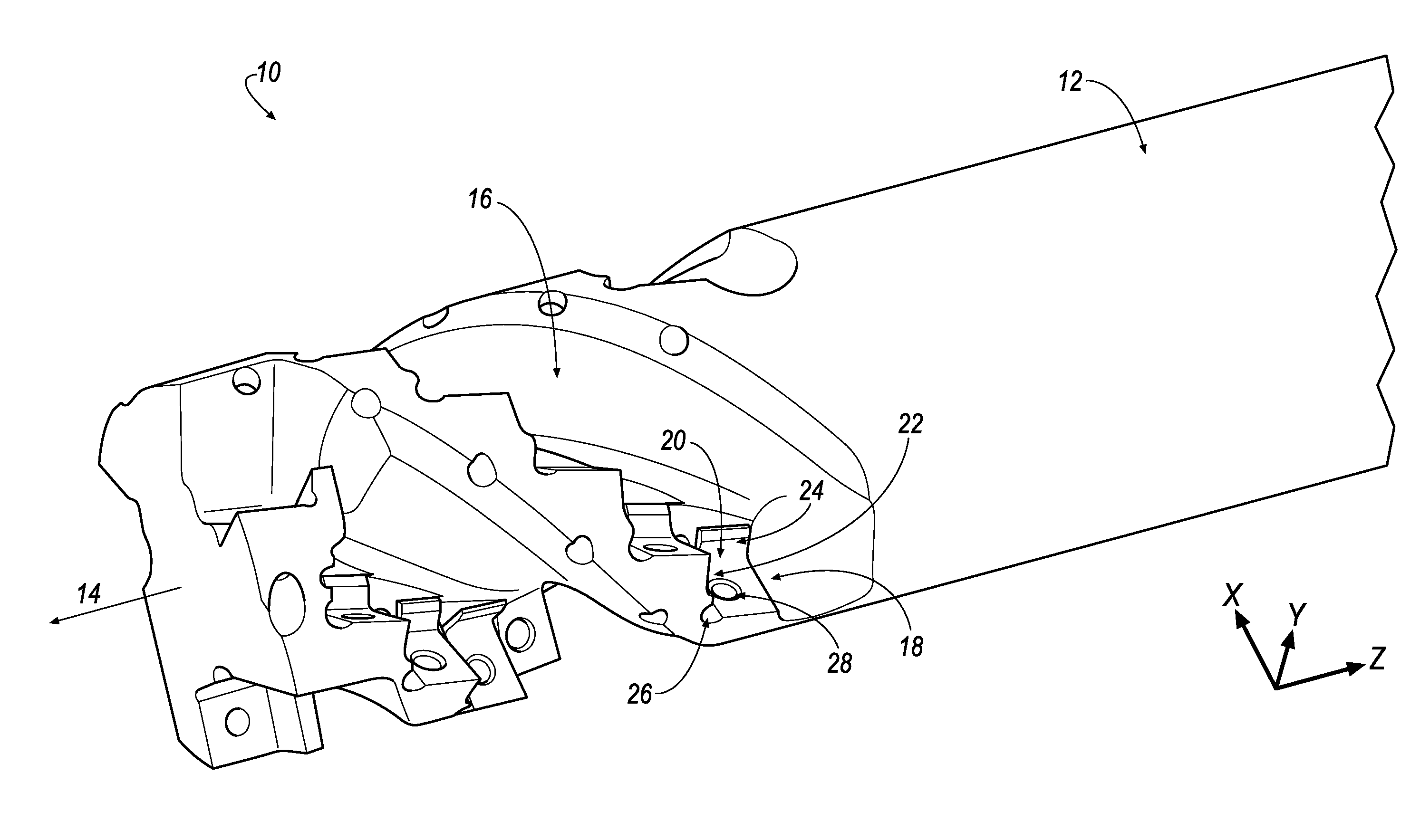
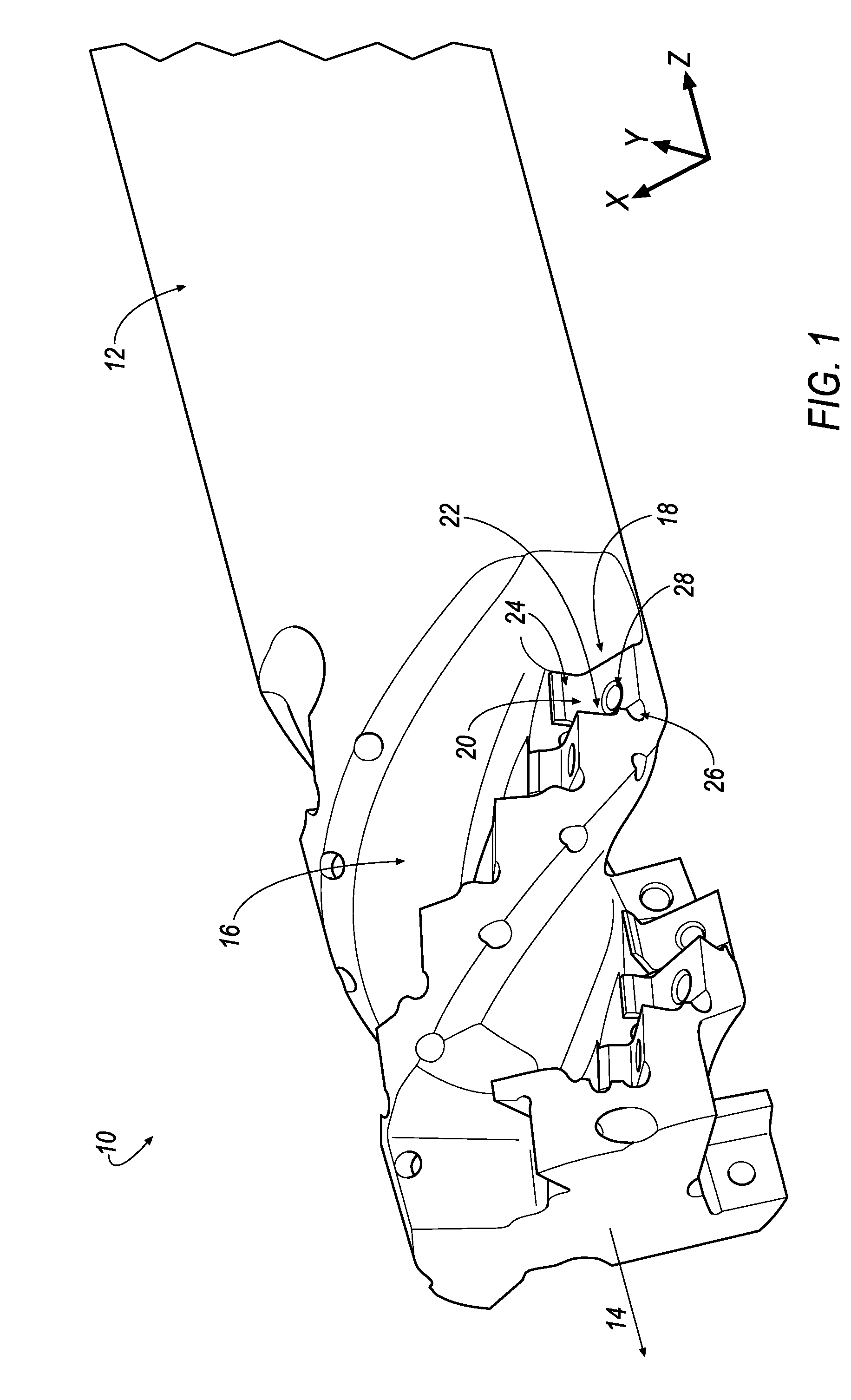
[0020]Referring to the drawings, wherein like reference characters represent like elements, there is shown in FIG. 1 a cutting tool 10 includes a generally cylindrical tool body 12 that is generally radially symmetrical about its rotational axis 14. The tool body 12 preferably, but not necessarily, includes a plurality of flutes 16 each bearing a plurality of pockets 18 therein. The pockets 18 are rotationally symmetrically arranged with respect to the axis 14. At least one, but possibly more, of the cutting inserts 12 are configured and dimensioned to be received within and secured to each pocket 18.

[0021]In the illustrated embodiment of FIG. 1, a cutting insert (not shown) can be received within and secured to a corresponding pocket 18. It will be appreciated that the invention is not limited by the number of pockets 18, and that the invention can be practiced with any desired number of pockets 18, depending on the dimensions of the tool body 12.

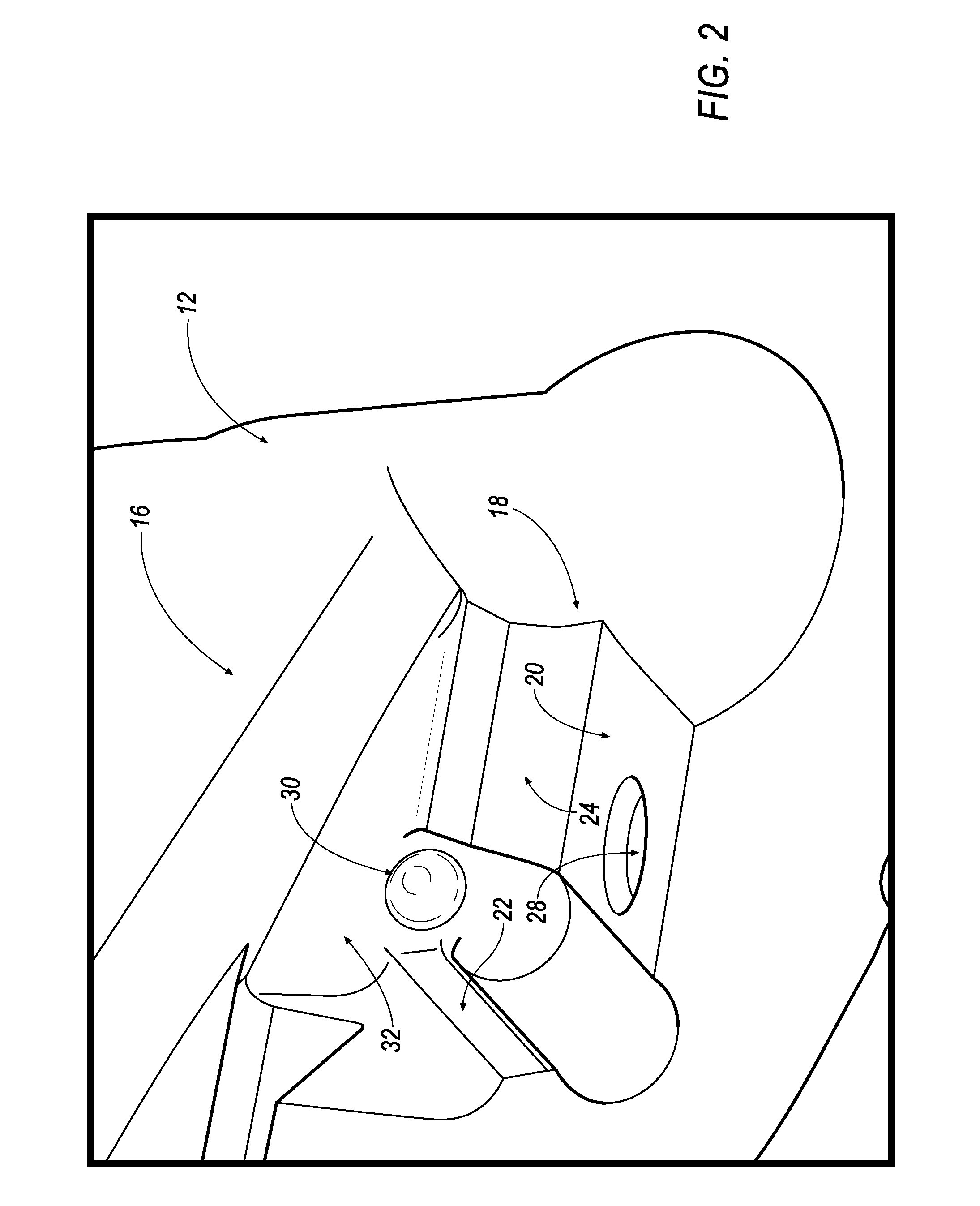
[0022]Each pocket 18 has a bottom s...


PUM

PropertyMeasurementUnit
tensile stressaaaaaaaaaa
radiusaaaaaaaaaa
radiusaaaaaaaaaa

Abstract

A cutting tool includes a tool body having a plurality of pockets for receiving cutting inserts. Each pocket includes a bottom support surface, an axial support surface, a radial support surface and a corner relief between the bottom support surface and the axial support surface. A pocket feature is at least partially located proximate the pocket, and more specifically, at least partially located on a wall between the axial support surface and the radial support surface for reducing a tensile stress of the cutting tool during a machining operation

Description

BACKGROUND OF THE INVENTION[0001]Cutting tools, such as milling cutters, are rotatable tools of cylindrical, conical, shaped or disk form, having a plurality of cutting edges. Such cutters are available in many forms, such as plain cylindrical, side milling cutters, face and end mills, formed cutters, and standard and special shaped profile cutters.[0002]End mills employing cutting inserts mounted at the front end of the tool are known in the art. The end mills can be used in several types of applications depending on the configuration of the cutting inserts mounted therein. The cutting inserts may present a peripheral cutting edge for side milling, a front cutting edge for face milling and a curved cutting edge of a so-called “ball-nose” end mill for various copying applications. Four flute mills are probably the most common, but 2, 3 or 6 flutes are also used extensively. End mills are in much used because they can execute a wide variety of milling operations, and the initial cost...

Claims


Application Information

Patent Timeline
Patent Type & Authority Applications(United States)
IPC IPC(8): B23C5/22B23B27/16
CPCB23C5/2208B23C5/109Y10T407/2202Y10T407/1906B23C2210/168Y10T407/1908Y10T407/2272Y10T407/192B23C5/06B23C5/22
Inventor FILHO, RUY FROTA DE SOUZAFRANCIS, MARK ALAN
Owner KENNAMETAL INC
Why Eureka
Try Eureka