Electric three-way valve

Active Publication Date: 2013-05-30
ZHEJIANG SANHUA CO LTD
View PDF13 Cites 7 Cited by
  • Summary
  • Abstract
  • Description
  • Claims
  • Application Information

AI Technical Summary

Benefits of technology

[0024]According to the aspect of the invention, the electric switching valve capable of selectively opening or closing the output ports in the valve seat is provided. Since the motor unit and the cylindrical casing accommodating the gear unit driven by the motor unit and the valve core rotationally driven by the gear unit are in

Problems solved by technology

Furthermore, in the typical valve core which rotates in a sliding manner, the shape of the val

Method used


Image

  • Electric three-way valve
  • Electric three-way valve
  • Electric three-way valve

Examples


Example

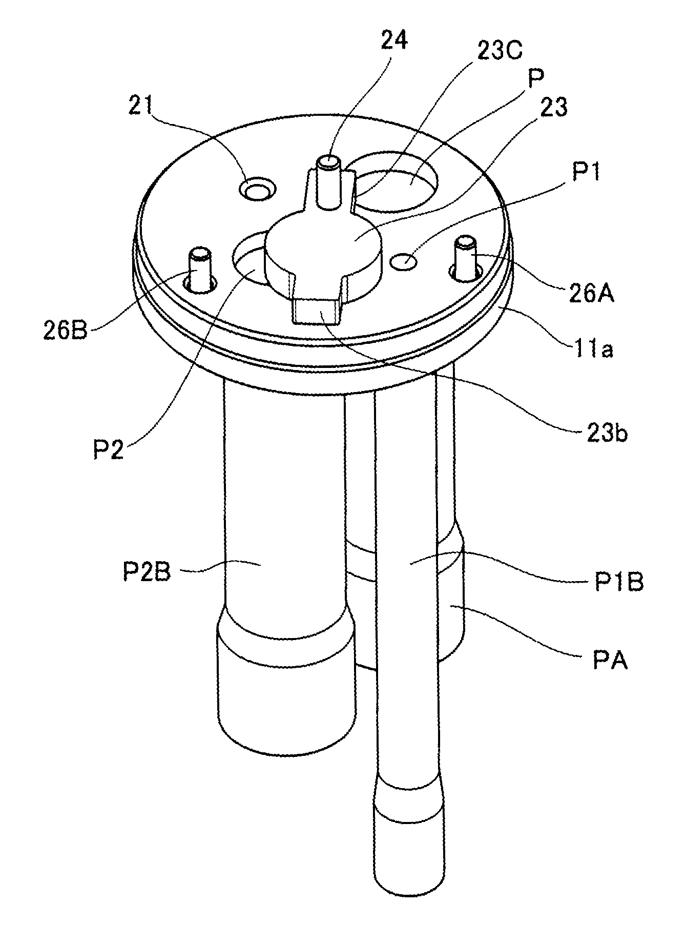
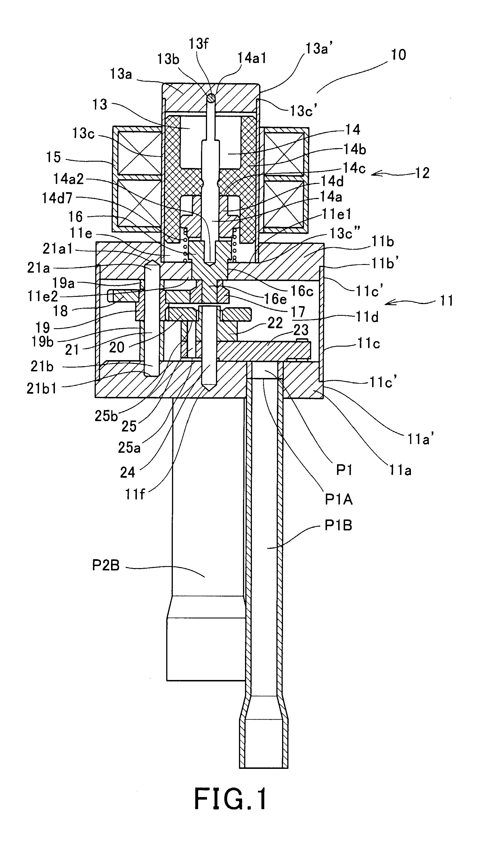
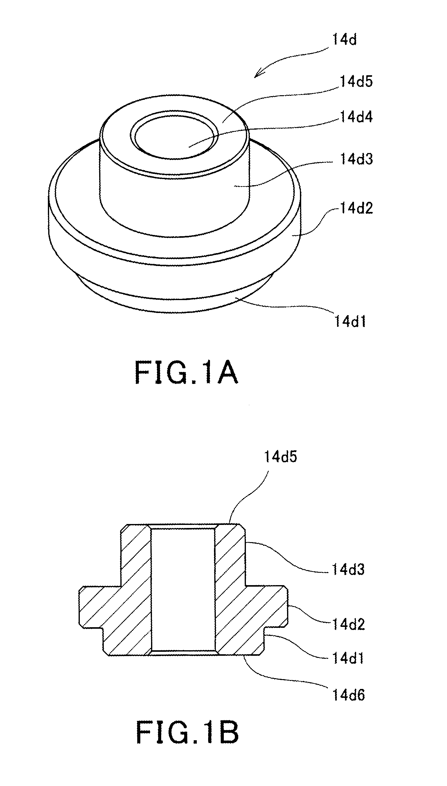
[0037]An electric three-way valve 10 as an electric switching valve illustrated in FIG. 1 includes a cylindrical casing 11 which is formed of a metal material, for example, stainless steel and a motor unit 12. The motor unit 12 includes a cylindrical housing 13 which is formed of a non-magnetic metal material, for example, stainless steel, a rotor 14 and a rotor shaft 14a which are disposed inside the housing, and a fixed coil 15 which is laid on the outside of the housing 13 and serves as a stator to drive the rotor 14, where the motor unit 12 is separated from the casing 11 and is disposed at the upper outer side of the casing 11 in the drawings.

[0038]The cylindrical casing 11 includes a disk-like valve seat (which is also called a valve seat surface) 11a which is formed of a metal material, for example, stainless steel, a disk-like plane plate 11b which is disposed so as to face the valve seat 11a, serves as an upper end surface, and is formed of a metal material, for example, st...


PUM


Abstract

An electric three-way valve comprises: an input port, a plurality of output ports and a valve core which rotates in a sliding manner in the valve seat by a driving force of a motor unit, wherein the valve core selectively opens or closes the plurality of output ports, the motor unit is attached as a separated constituent to an outside of an upper end surface of a cylindrical casing introducing refrigerant, the valve core is driven by a gear unit which transmits the driving force of the motor unit and is disposed inside the cylindrical casing, the cylindrical casing includes one opening portion and a side wall with an apex portion, a housing which is fixed to a cylindrical wall portion of the apex portion and is equipped with the motor unit is uprightly formed in the other opening portion, and the housing is attached to the cylindrical casing.

Description

BACKGROUND OF THE INVENTION[0001]1. Field of the Invention[0002]The present invention relates to an electric three-way valve which circulates refrigerant of an air-conditioner and a refrigerator and switches a passageway.[0003]2. Description of the Related Art[0004]In general, there is known a valve which uses a motor, for example, a step motor, installs a gear in a shaft end portion of a rotor of the motor, and blocks one passageway opened to a valve seat by rotating a valve core in the valve seat in a sliding manner using a driving force generated by the meshing between the gear and a gear driving the valve core (see Japanese Patent Literature 1, that is, JP 03-28583 A). Furthermore, there is known a valve which controls an opening degree of an opening by a valve core driven so as to slide on a valve seat by a driving force generated by a gear as described above (see Japanese Patent Literature 2, that is, JP 2000-346227 A).[0005]In the typical valve which uses the valve core rotat...

Claims


Application Information

Patent Timeline
IPC IPC(8): F16K31/04F16K11/06
CPCF16K11/06F16K31/041F16K31/04F16K11/0743Y10T137/8782Y10T137/86855Y10T137/87732F25B41/20F16K11/072
Inventor LIN, YANWEIHUI, XUMINGFENG, DINGSHUAICHEN, BIN
Owner ZHEJIANG SANHUA CO LTD
Why Eureka
Try Eureka