
Active MIMO antenna configuration for maximizing throughput in mobile devices

a mobile device and active technology, applied in the field of wireless communication, can solve the problems of affecting the throughput performance of the communication link and the problem of exacerbated problems, and achieve the effect of optimizing the antenna performan

Active Publication Date: 2013-05-30
KYOCERA AVX COMPONENTS (SAN DIEGO) INC
View PDF7 Cites 16 Cited by
  • Summary
  • Abstract
  • Description
  • Claims
  • Application Information

AI Technical Summary

Benefits of technology

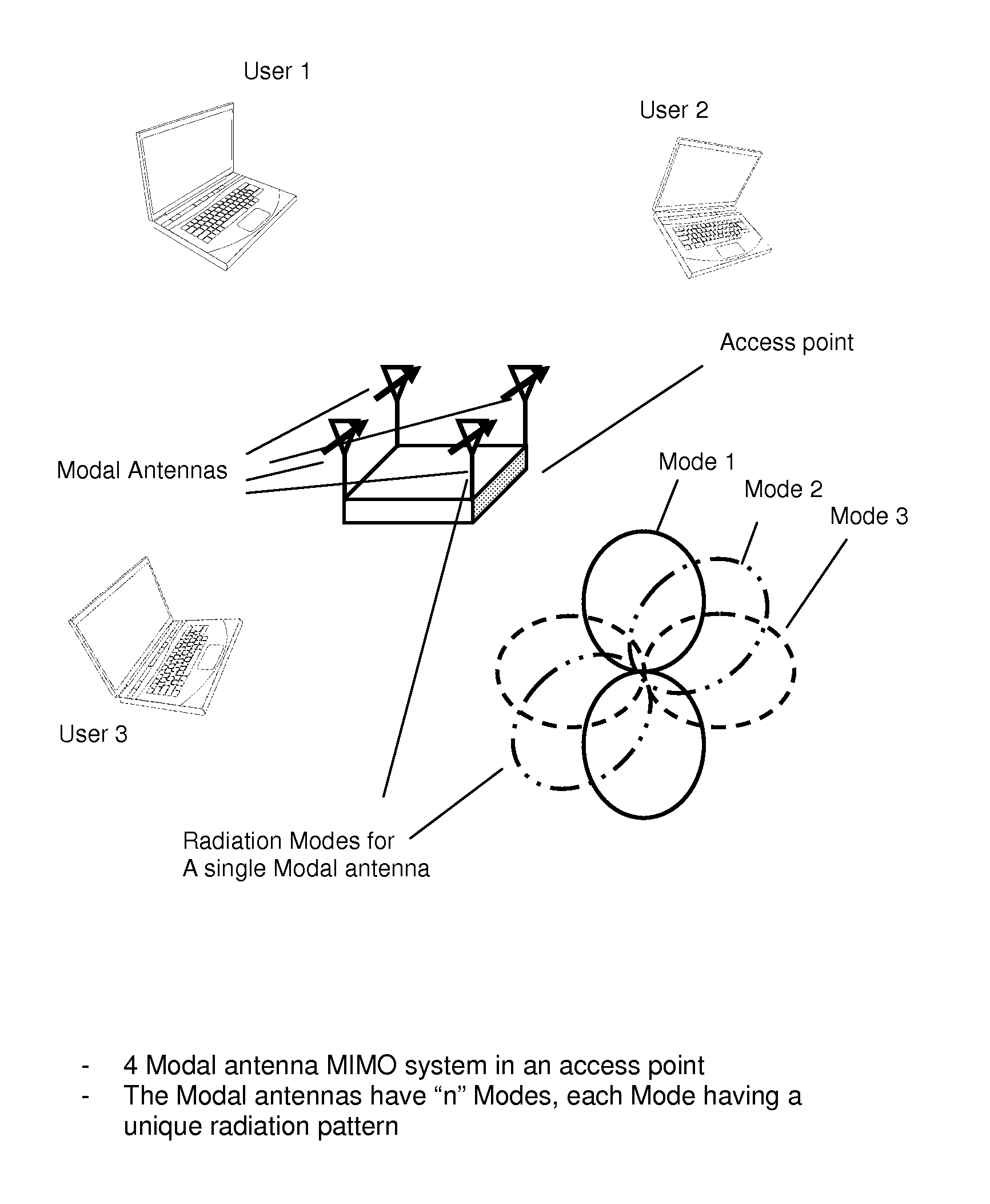
The patent text describes an active MIMO antenna system that can selectively operate in multiple modes to optimize its performance. The system includes multiple antennas that produce distinct radiation patterns in each mode. A processor controls which mode the antennas should operate in to alter the correlation of the system and achieve optimal performance. Overall, the patent describes a technical solution for improving the efficiency and performance of active MIMO antennas.

Problems solved by technology

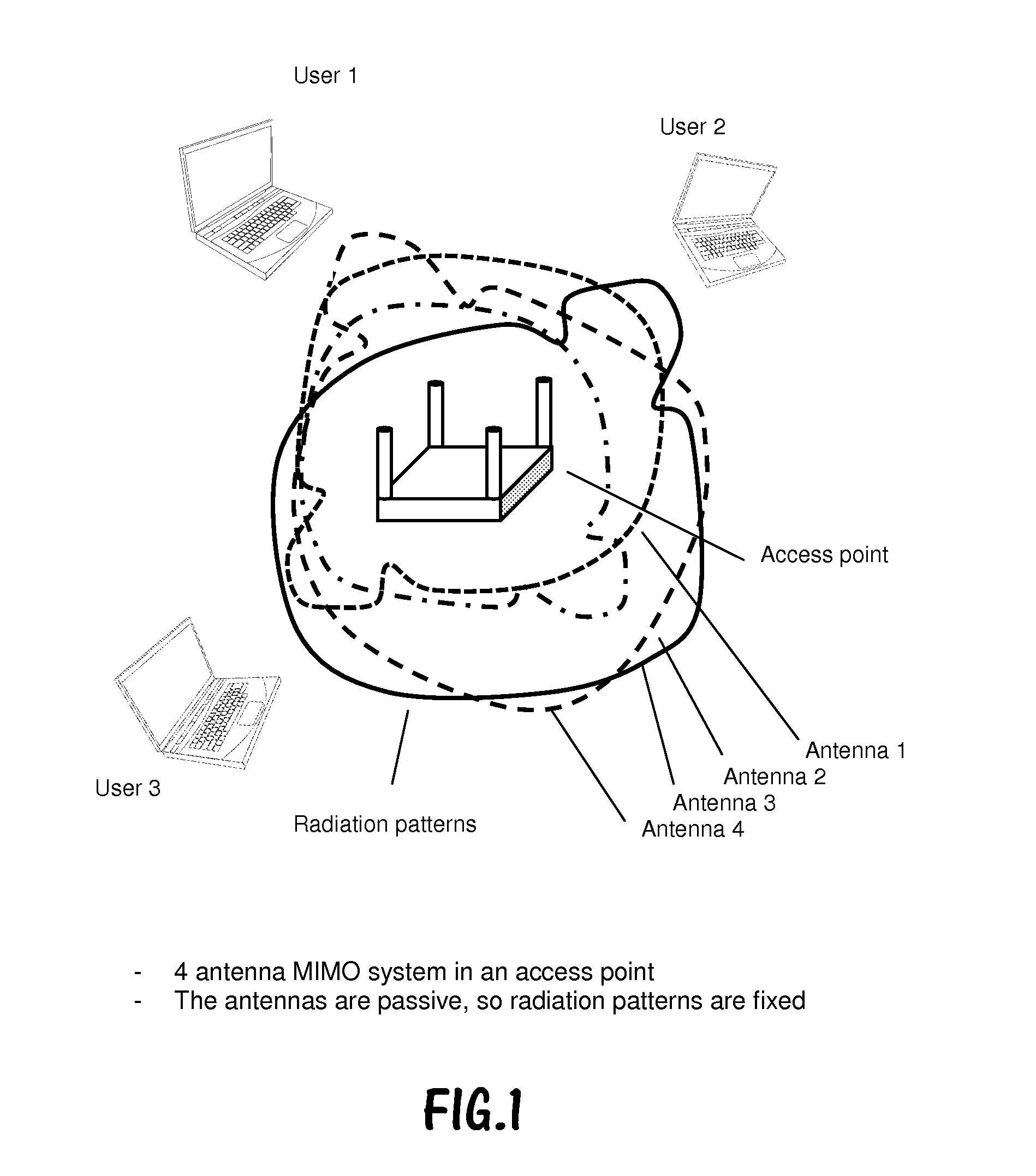
For handheld mobile devices the problem is exacerbated by antenna detuning caused by the multiple use cases of a device: hand loading of the cell phone, cell phone placed to user's head, cell phone placed on metal surface, etc.
For both cell phone and access point applications, the multipath environment is constantly changing, which impacts throughput performance of the communication link.

Method used


Image

  • Active MIMO antenna configuration for maximizing throughput in mobile devices
  • Active MIMO antenna configuration for maximizing throughput in mobile devices
  • Active MIMO antenna configuration for maximizing throughput in mobile devices

Examples


Embodiment Construction

[0033]In the following description, for purposes of explanation and not limitation, details and descriptions are set forth in order to provide a thorough understanding of the present invention. However, it will be apparent to those skilled in the art that the present invention may be practiced in other embodiments that depart from these details and descriptions.

[0034]Commonly owned, U.S. Pat. No. 7,911,402, titled “ANTENNA AND METHOD FOR STEERING ANTENNA BEAM DIRECTION”, and U.S. Pat. No. 7,830,320, titled “ANTENNA WITH ACTIVE ELEMENTS”, disclose antenna systems capable of beam steering, band switching, active matching, and other active tunable characteristics; the contents of each of which are hereby incorporated by reference. These antennas utilize a radiating element and one or more parasitic elements coupled to active elements in a manner for enabling switching, variable reactance, and other tuning of the antenna components. The resulting structure is an active tunable antenna c...


PUM


Abstract

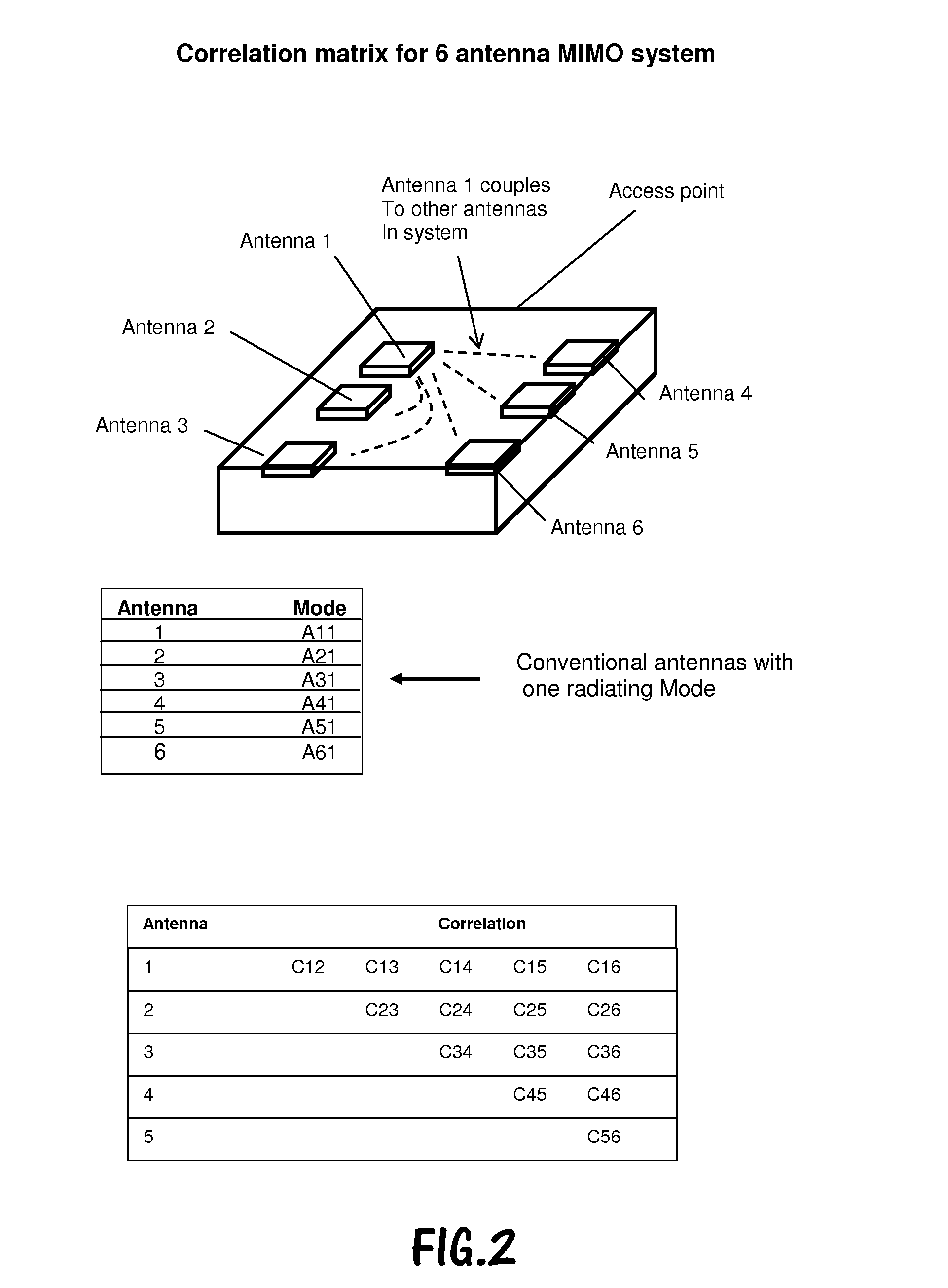
An active antenna system and algorithm is proposed that provides for dynamic tuning and optimization of antenna system parameters for a MIMO system that will provide for greater throughput. As one or multiple antennas are loaded or de-tuned due to environmental changes, corrections to correlation and / or isolation are made by tuning the active antenna. A null-steering technique is implemented to alter the near-field and far-field characteristics to aid in modifying correlation and isolation in the multi-antenna system.

Description

CROSS-REFERENCE TO RELATED APPLICATIONS[0001]This application is a CIP of U.S. Ser. No. 13 / 029,564, filed Feb. 17, 2011, and titled “ANTENNA AND METHOD FOR STEERING ANTENNA BEAM DIRECTION”, which is a CON of U.S. Ser. No. 12 / 043,090, filed Mar. 5, 2008, titled “ANTENNA AND METHOD FOR STEERING ANTENNA BEAM DIRECTION”, now issued as U.S. Pat. No. 7,911,402; and[0002]a CIP of U.S. Ser. No. 13 / 227,361, filed Sep. 7, 2011, and titled “MODAL ANTENNA WITH CORRELATION MANAGEMENT FOR DIVERSITY APPLICATIONS”;[0003]the contents of each of which are hereby incorporated by reference.BACKGROUND OF THE INVENTION[0004]1. Field of the Invention[0005]This invention relates generally to the field of wireless communication. In particular, the invention relates to Multiple Input Multiple Output (MIMO) antenna implementations capable of improved data throughput performance for use in such wireless communications.[0006]2. Description of the Related Art[0007]Commonly owned U.S. Pat. No. 7,911,402 describes...

Claims


Application Information

Patent Timeline
IPC IPC(8): H01Q21/28H01Q25/04
CPCH01Q21/28H01Q25/04H01Q9/0421H01Q3/00H01Q1/243
Inventor DESCLOS, LAURENTMATSUMORI, BARRYROWSON, SEBASTIANSINGH, ABHISHEK
Owner KYOCERA AVX COMPONENTS (SAN DIEGO) INC
Learn More