Apparatus and method for improved processing of food products

Inactive Publication Date: 2013-05-30
REFLECTRONICS
View PDF12 Cites 13 Cited by
  • Summary
  • Abstract
  • Description
  • Claims
  • Application Information

AI Technical Summary

Benefits of technology

[0009]The first light transmission fiber projects light from the light source as a light cone through the sapphire window into the product being monitored. The first light collecting fiber collects backscatter light from the product in a detection cone passing through the sapphire window and converging toward the first light collecting fiber. The first light transmission fiber and first light collecting fiber are oriented so that the light cone and detection cone define a first point of overlap on a product side of the sapphire window. More specifically, the sapphire

Problems solved by technology

While diffuse reflectance from the product surface does carry information about the property of the product, that information is relatively limited.
While a direct contact optical contact fiber configuration of the type described above and illustrated in FIG. 1 has the advantage that the light is delivered directly to the product, there are problems associated with a direct contact optical fiber configuration.
The foremost challenge is in manufacture and mor

Method used


Image

  • Apparatus and method for improved processing of food products
  • Apparatus and method for improved processing of food products
  • Apparatus and method for improved processing of food products

Examples


example 1

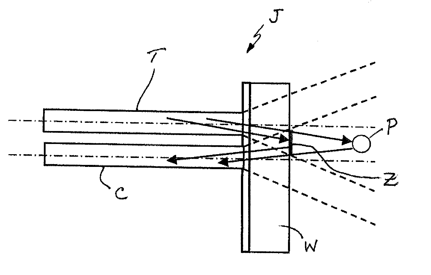
[0050]A probe was made with metal coated fiber optics to prevent crosstalk between the fibers. The fibers used for the transmission of incident light and the collection of backscatter light had an outer diameter of 287 microns. The fiber core was 200 microns, cladding 220 microns in diameter. The fibers had a numerical aperture of 0.12 that reduced the cone spread of light and minimized the distance between the delivery fiber and the receiving fiber. The thickness of the optical grease was 127 microns with a numerical aperture of 1.6. The thickness of the sapphire window was 635 microns with a numerical aperture of 1.5. The diameter of the cone of the light increased from 200 microns at the fiber optical grease interface to 219 microns at the optical grease-sapphire window interface to 260 microns at the sapphire window-product interface. Consequently the minimum separation distance between the centerline of the delivery fiber and the centerline of the receiving fiber in order to av...

example 2

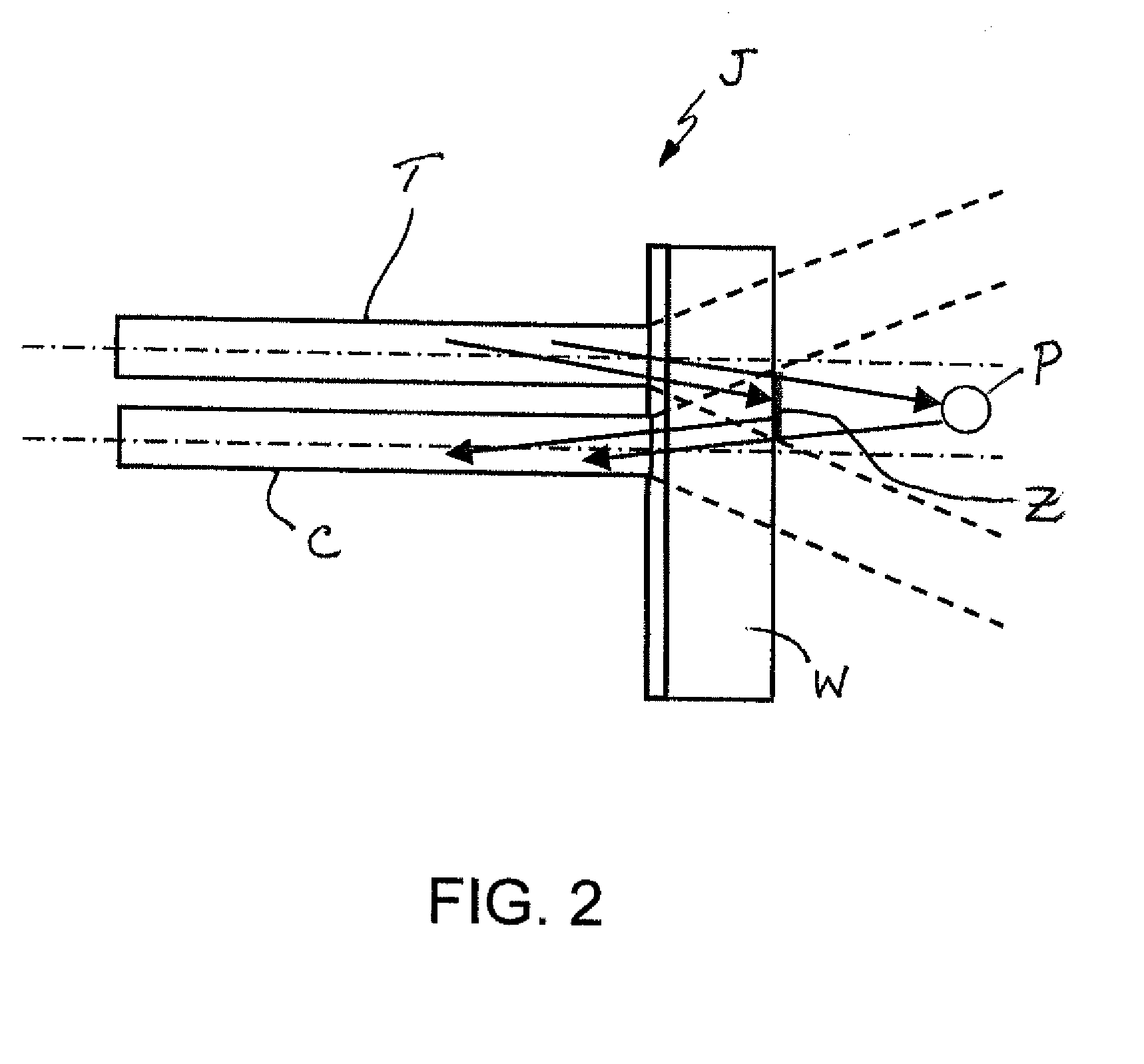
[0051]A probe is made with transmission and receiving fibers having a 0.22 numerical aperture. The cone diameters at the fiber-grease, grease-sapphire and sapphire-product interfaces are 200, 235 and 423 microns respectively. As a consequence, in order to avoid specular and diffuse reflectance the minimum separation distance for the delivery and receiving fibers using the numerical aperture 0.22 fiber is 423 microns. Since the fiber has a diameter with cladding of 287 microns then there must be a 137 micron space between the fibers.

[0052]The foregoing has been presented for purposes of illustration and description. It is not intended to be exhaustive or to limit the embodiments to the precise form disclosed. Obvious modifications and variations are possible in light of the above teachings. For example, while the probe and method are described as being used to monitor the coagulation of milk in the cheese making process, they could be used to monitor and measure other compositions an...


PUM


Abstract

The light backscatter probe includes a housing carrying at least one optical transmission fiber and two optical reception or collecting fibers. The ends of the fibers are closed by a sapphire window. First and second light sources are provided for projecting incident light onto a product outside the sapphire window. The reception paths or fibers are located at different radial distances from the one optical transmission path to allow for measuring the coagulation of dairy products or determination of compositions of food products.

Description

[0001]This utility patent application claims the benefit of priority in U.S. Provisional Patent Application Ser. No. 61 / 565,091 filed on Nov. 30, 2011, the entirety of the disclosure of which is incorporated herein by reference.TECHNICAL FIELD[0002]This document relates generally to an apparatus and method for accurately monitoring a response or measuring a physical property during the processing of food products and more specifically dairy products processing including the steps of coagulation of milk; the status of the syneresis step; fat and protein content measurement in whey processing; measurement of fat in process liquid milk products; coagulation of milk in cultured products such as cottage cheese and yogurt.BACKGROUND OF THE INVENTION[0003]Apparatus and methods for improving the processing of cheese products are well known in the art. U.S. Pat. No. 5,172,193 to Payne et al. discloses a particularly useful apparatus and method for this purpose. As disclosed in this document,...

Claims


Application Information

Patent Timeline
IPC IPC(8): G01N21/49
CPCG01N21/49G01N21/51G01N21/474
Inventor PAYNE, FRED A.
Owner REFLECTRONICS
Why Eureka
Try Eureka