Microphone and Method for Calibrating a Microphone

a microphone and microphone technology, applied in the direction of transducer details, electrical transducers, electrostatic transducer microphones, etc., can solve the problems of controlling the physical and mechanical parameters of these devices

Active Publication Date: 2013-05-30
INFINEON TECH AG
View PDF8 Cites 37 Cited by
  • Summary
  • Abstract
  • Description
  • Claims
  • Application Information

AI Technical Summary

Benefits of technology

[0008]In accordance with an embodiment of the invention an apparatus comprises a MEMS device for sensing an acoustic signal, a bias voltage source for ...

Problems solved by technology

A significant problem in the production of MEMS devices is t...

Method used


Image

  • Microphone and Method for Calibrating a Microphone
  • Microphone and Method for Calibrating a Microphone
  • Microphone and Method for Calibrating a Microphone

Examples


Embodiment Construction

[0013]The making and using of the presently preferred embodiments are discussed in detail below. It should be appreciated, however, that the present invention provides many applicable inventive concepts that can be embodied in a wide variety of specific contexts. The specific embodiments discussed are merely illustrative of specific ways to make and use the invention, and do not limit the scope of the invention.

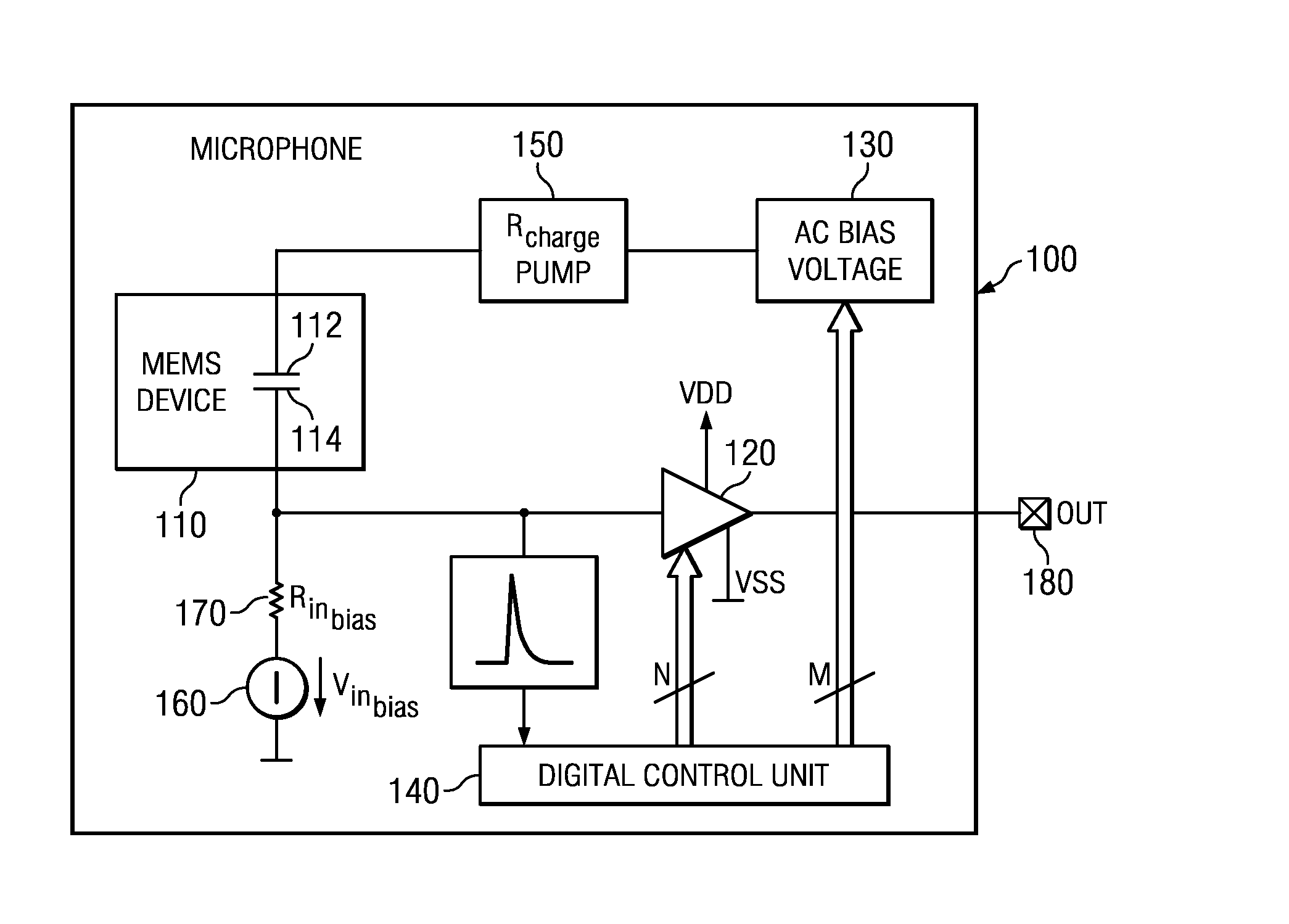
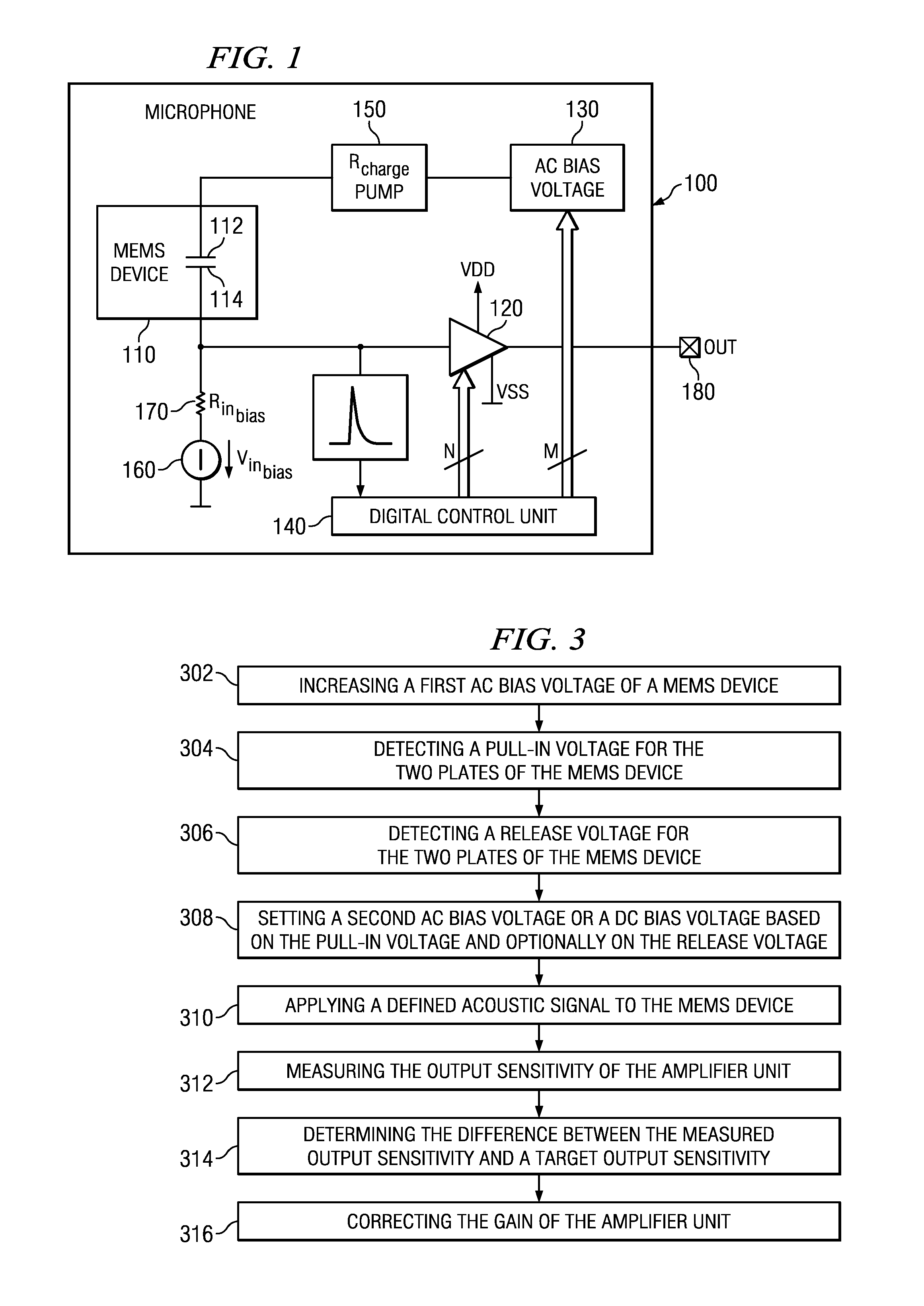
[0014]The present invention will be described with respect to embodiments in a specific context, namely a microphone. The invention may also be applied, however, to other types of systems such as audio systems, communication systems, or sensor systems.

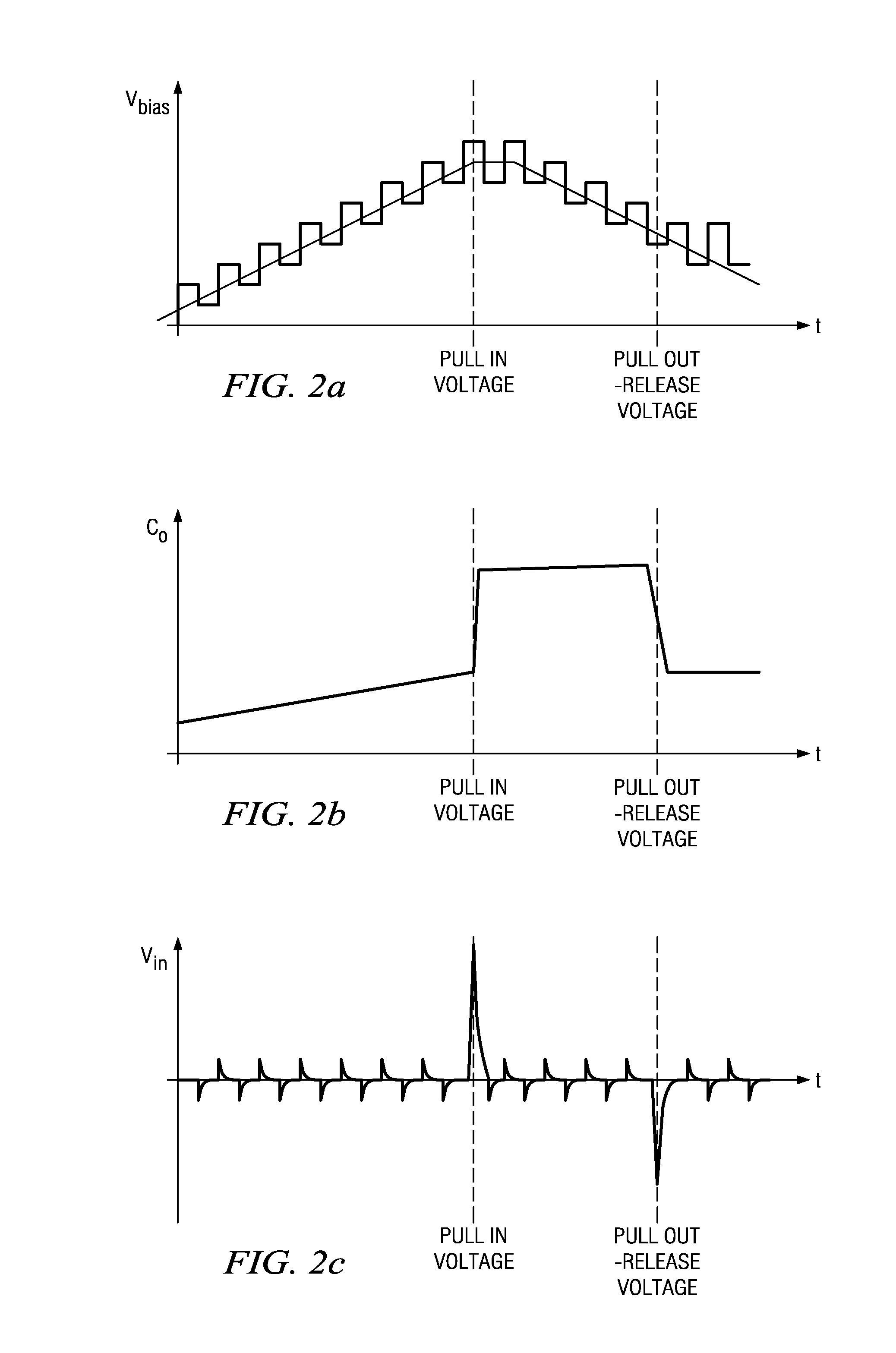
[0015]In a condenser microphone or capacitor microphone, a diaphragm or membrane and a backplate form the electrodes of a capacitor. The diaphragm responds to sound pressure levels and produces electrical signals by changing the capacitance of the capacitor.

[0016]The capacitance of the microphone is a function of the applied bia...


PUM


Abstract

A microphone and a method for calibrating a microphone are disclosed. In one embodiment the method for calibrating a microphone comprises operating a MEMS device based on a first AC bias voltage, measuring a pull-in voltage, calculating a second AC bias voltage or a DC bias voltage, and operating the MEMS device based the second AC bias voltage or the DC bias voltage.

Description

TECHNICAL FIELD[0001]The present invention relates generally to a microphone and a method for calibrating a microphone.BACKGROUND[0002]MEMS (microelectromechancial system) devices are generally manufactured in large numbers on semiconductor wafers.[0003]A significant problem in the production of MEMS devices is the control of physical and mechanical parameters of these devices. For example, parameters such as mechanical stiffness, electrical resistance, diaphragm area, air gap height, etc. may vary by about + / −20% or more.[0004]The variations of these parameters on the uniformity and performance of the MEMS devices may be significant. In particular, parameter variations are especially significant in a high volume and low-cost MEMS (microphones) manufacturing process where the complexity is low. Consequently, it would be advantageous to compensate for these parameter variations.SUMMARY OF THE INVENTION[0005]In accordance with an embodiment of the present invention a method for calibr...

Claims


Application Information

Patent Timeline
IPC IPC(8): H04R29/00H04R3/00
CPCH04R3/06H04R29/004H04R19/005H04R19/04H04R29/00
Inventor HAMMERSCHMIDT, DIRKKROPFITSCH, MICHAELWIESBAUER, ANDREAS
Owner INFINEON TECH AG
Why Eureka
Try Eureka