Power source apparatus, and vehicle and power storage system equipped with the power source apparatus

Inactive Publication Date: 2013-05-30
SANYO ELECTRIC CO LTD
View PDF4 Cites 18 Cited by
  • Summary
  • Abstract
  • Description
  • Claims
  • Application Information

AI Technical Summary

Benefits of technology

The present invention provides a power source apparatus with improved flexibility in the spatial arrangement of battery blocks. The apparatus includes battery blocks with endplates and floor-panels that can be attached to each other, allowing for vertical layering. The attachment of battery blocks can be done with fastener material inserted through upper and lower attachment sections, and there is no need for additional floor-panel supporting structures on the battery cells within the battery blocks. The floor-panels can be attached to a base-panel or floor-panel with the upper attachment sections, and the battery blocks can be attached on the upper surface of a floor-panel with the lower attachment sections. The attachment of battery blocks to floor-panels can be done with blind-nuts or T-nuts, which simplifies the attachment process and reduces labor costs. The power source apparatus can be partitioned into two or three layers, and there is no need for additional space for nuts on the floor-panels and base-panel.

Problems solved by technology

However, if a large number of battery blocks are used in this configuration, the dedicated area (footprint) of the case will increase proportionally with the number of battery blocks.
When many battery blocks have to be disposed in a limited space such as in a vehicle power source apparatus, strict space limits apply and installation of a power source apparatus that holds many battery blocks in a large case is problematic.
Unfortunately, these operations entail additional processing steps and increase cost.
As a result, case bulkiness becomes a problem.
For the original objective of disposing as many battery blocks as possible in a limited space, increasing the bulkiness of the case is counter productive.

Method used


Image

  • Power source apparatus, and vehicle and power storage system equipped with the power source apparatus
  • Power source apparatus, and vehicle and power storage system equipped with the power source apparatus
  • Power source apparatus, and vehicle and power storage system equipped with the power source apparatus

Examples


first embodiment

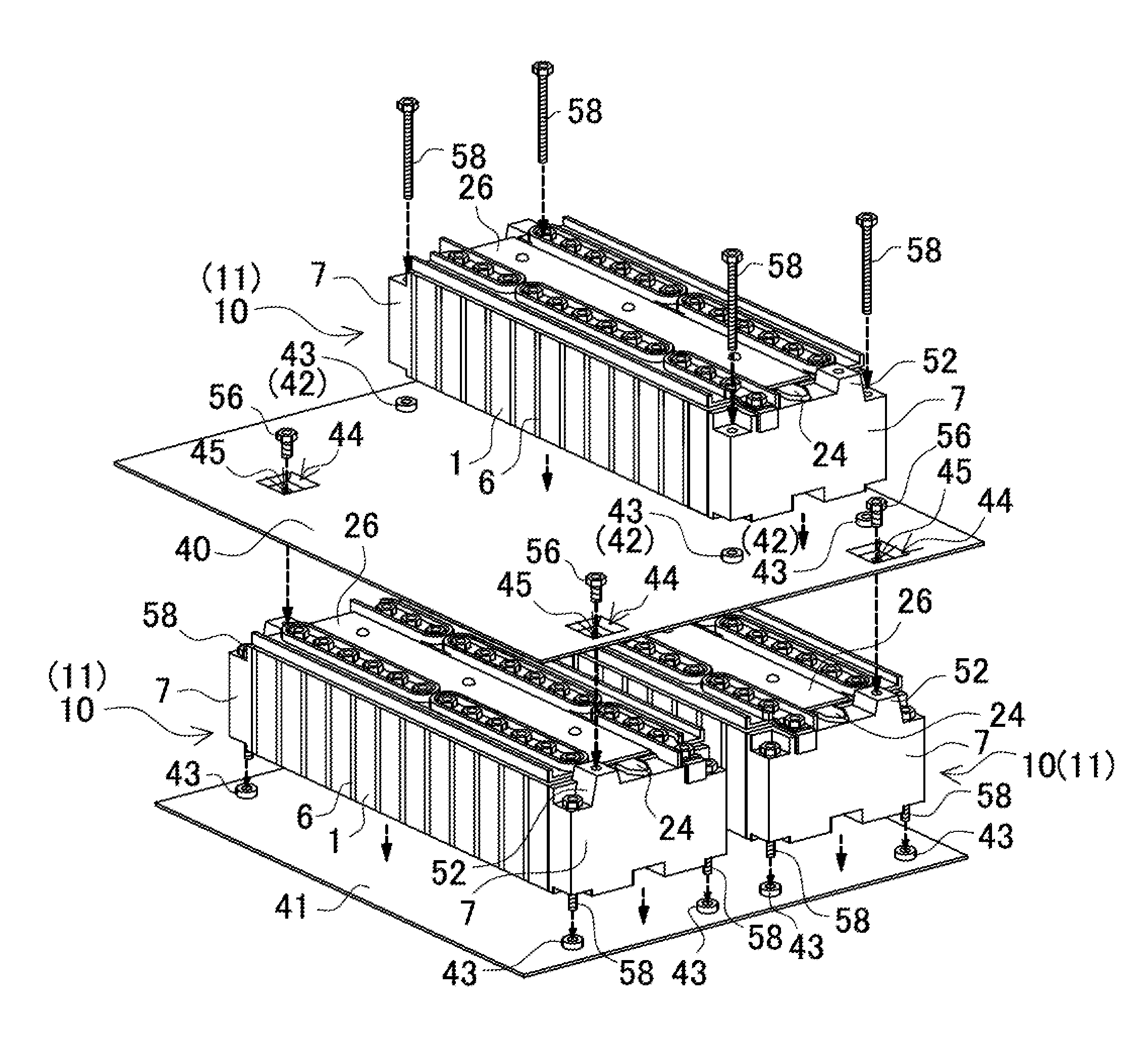
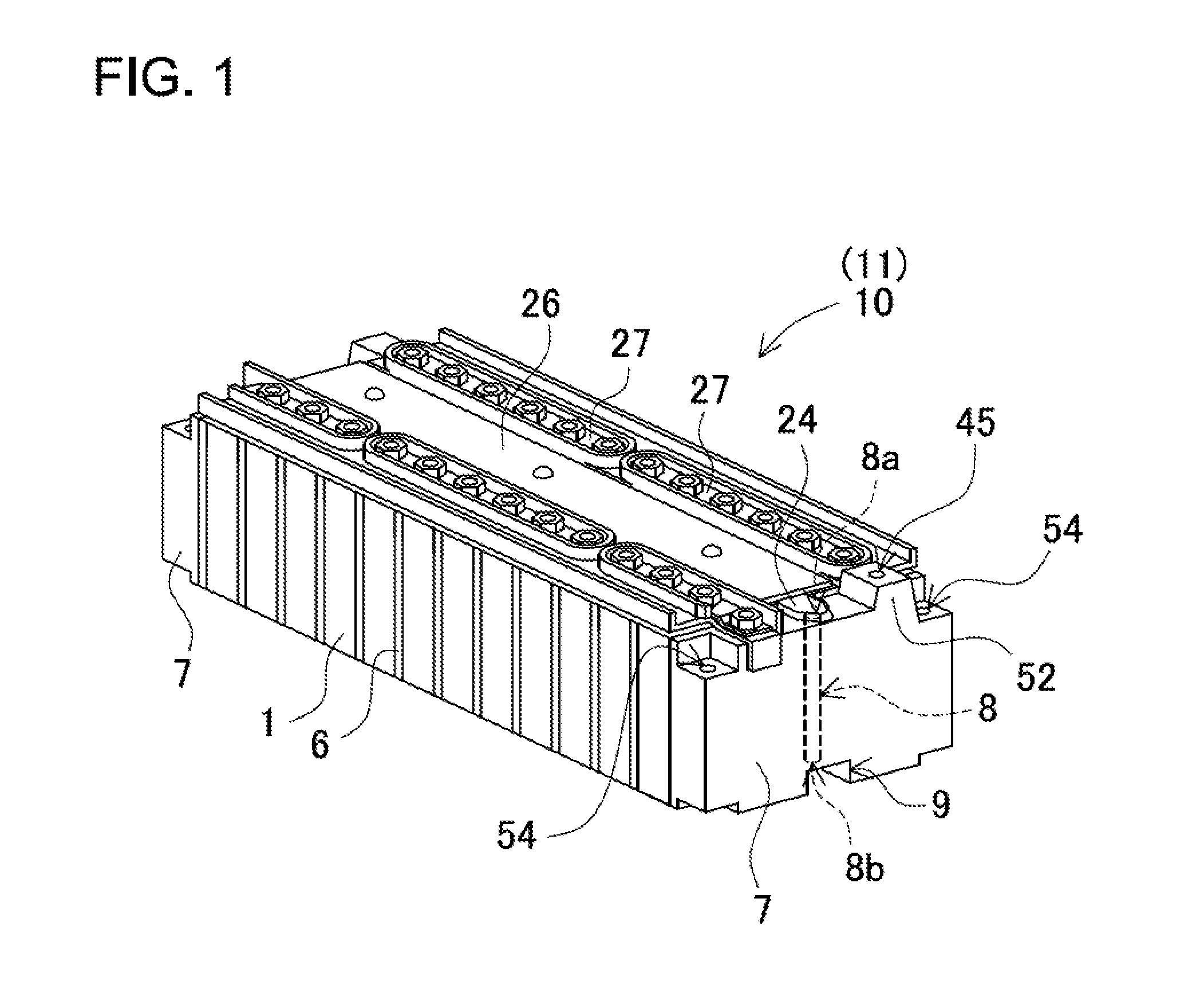
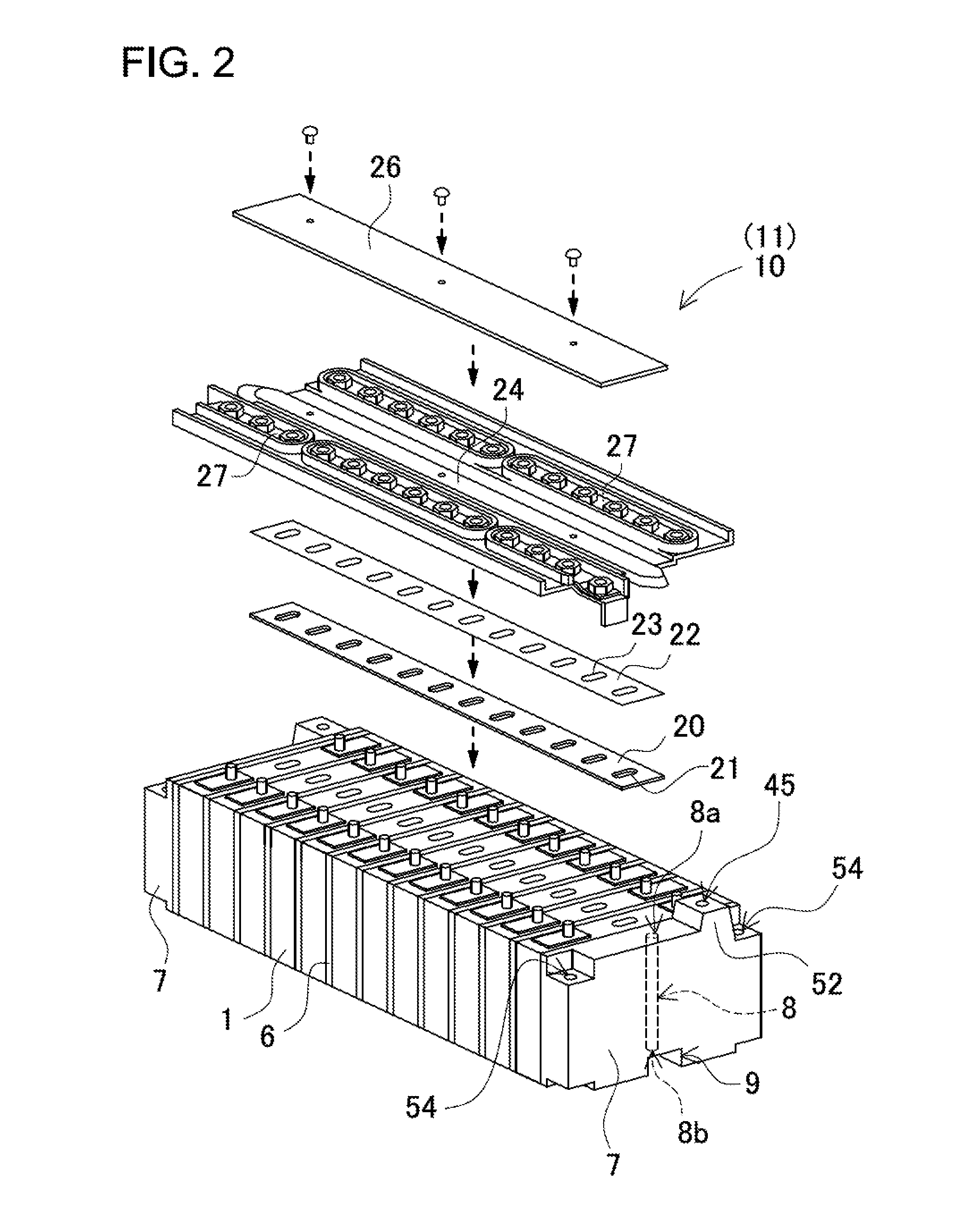
[0039]Based on FIGS. 1-3, the following describes an example of a power source apparatus used in an automotive application as the first embodiment. FIG. 1 shows an oblique view of the external appearance of a battery block 10 included in the power source apparatus, FIG. 2 shows an exploded oblique view with the safety valve gas duct 24, pressure plate 22, and sealing material 20 separated from the power source apparatus of FIG. 1, and FIG. 3 shows an exploded oblique view with a battery cell 1, separator 6, and endplate 7 separated from the power source apparatus of FIG. 1. As shown in FIG. 1, the battery block 10 has a box-shape. The power source apparatus is formed from a series and / or parallel connection of a plurality of these battery blocks 10. As shown in the exploded oblique view of FIG. 2, each battery block 10 is provided with a stack of a plurality of battery cells 1, sealing material 20, a pressure plate 22, and a safety valve gas duct 24. The safety valve gas duct 24 is ...


PUM


Abstract

The power source apparatus is made up of an arrangement of a plurality of battery blocks having a plurality of rectangular battery cells with endplates disposed at the ends. A base-panel that carries battery blocks disposed in a horizontal plane, and floor-panels disposed on top of battery blocks and configured with upper surfaces capable of carrying other battery blocks are provided. Battery block endplates have upper attachment sections to attach a floor-panel disposed on the upper surfaces of the endplates, and lower attachment sections to attach a base-panel or floor-panel disposed at the lower surfaces of the endplates.

Description

BACKGROUND OF THE INVENTION[0001]1. Field of the Invention[0002]The present invention relates to a power source apparatus having a plurality of stacked rectangular battery cells, to a vehicle and power storage system equipped with the power source apparatus; in particular, to a power source apparatus installed on-board an electric vehicle such as a hybrid vehicle, fuel-cell vehicle, electric vehicle, or electric auto-bike; or to a power source apparatus configured to supply high current such as in a home or industrial power storage application.[0003]2. Description of the Related Art[0004]A power source apparatus with a plurality of battery cells is used, for example, in automotive applications as the power source in a vehicle such as a hybrid vehicle or electric vehicle. This type of power source apparatus is made up of battery blocks having a plurality of stacked battery cells. In particular, recent demand for high power output has resulted in adoption of configurations that are co...

Claims


Application Information

Patent Timeline
IPC IPC(8): H01M2/10H01M50/209H01M50/262
CPCH01M2/1077Y02E60/10H01M50/209H01M50/262
Inventor KUROKAWA, YOSHIHIROKUME, MASAO
Owner SANYO ELECTRIC CO LTD
Why Eureka
Try Eureka