
Biological information detection device

Active Publication Date: 2013-05-30
SEIKO INSTR INC
View PDF14 Cites 14 Cited by
  • Summary
  • Abstract
  • Description
  • Claims
  • Application Information

AI Technical Summary

Benefits of technology

The present invention aims to provide a biological information detection device that can prevent faulty detection while maintaining good condition. The device has a biological signal detection portion integrated with the main body, while the fixing portion is detachably attached to the main body. This allows for easy cleaning and separation of the biological signal detection portion from the fixing portion, reducing the risk of defects in electrical parts.

Problems solved by technology

For this reason, there is concern of the electrical connection portions being corroded or foreign substances infiltrating into the electrical connection portions due to exposure of each of the electrical connection portions to the external environment such as sweat, which leads to an occurrence of defective detection.
In addition to this, there is concern of the electrode portion being exposed to a cleaning solution in association with cleaning of the strap at the time of maintenance, and thus the electrical parts such as the electrode and the electrical connection portion being damaged.

Method used


Image

  • Biological information detection device
  • Biological information detection device
  • Biological information detection device

Examples


first embodiment

Heartbeat Measurement Device

[0038]Next, a first embodiment of the present invention will be described with reference to FIGS. 1 to 9.

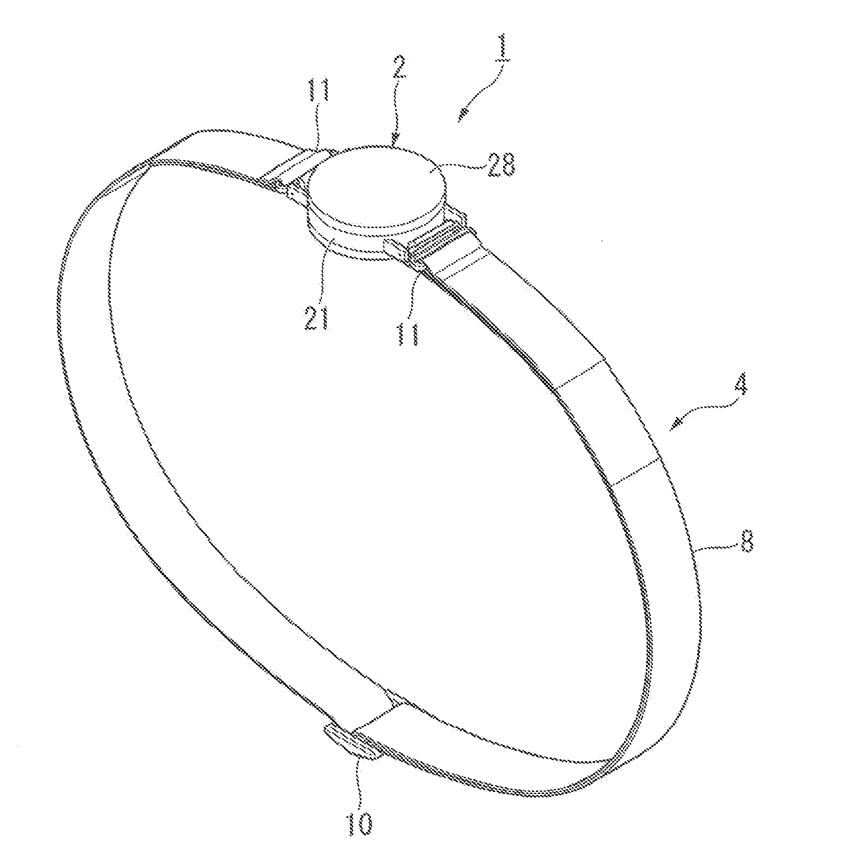
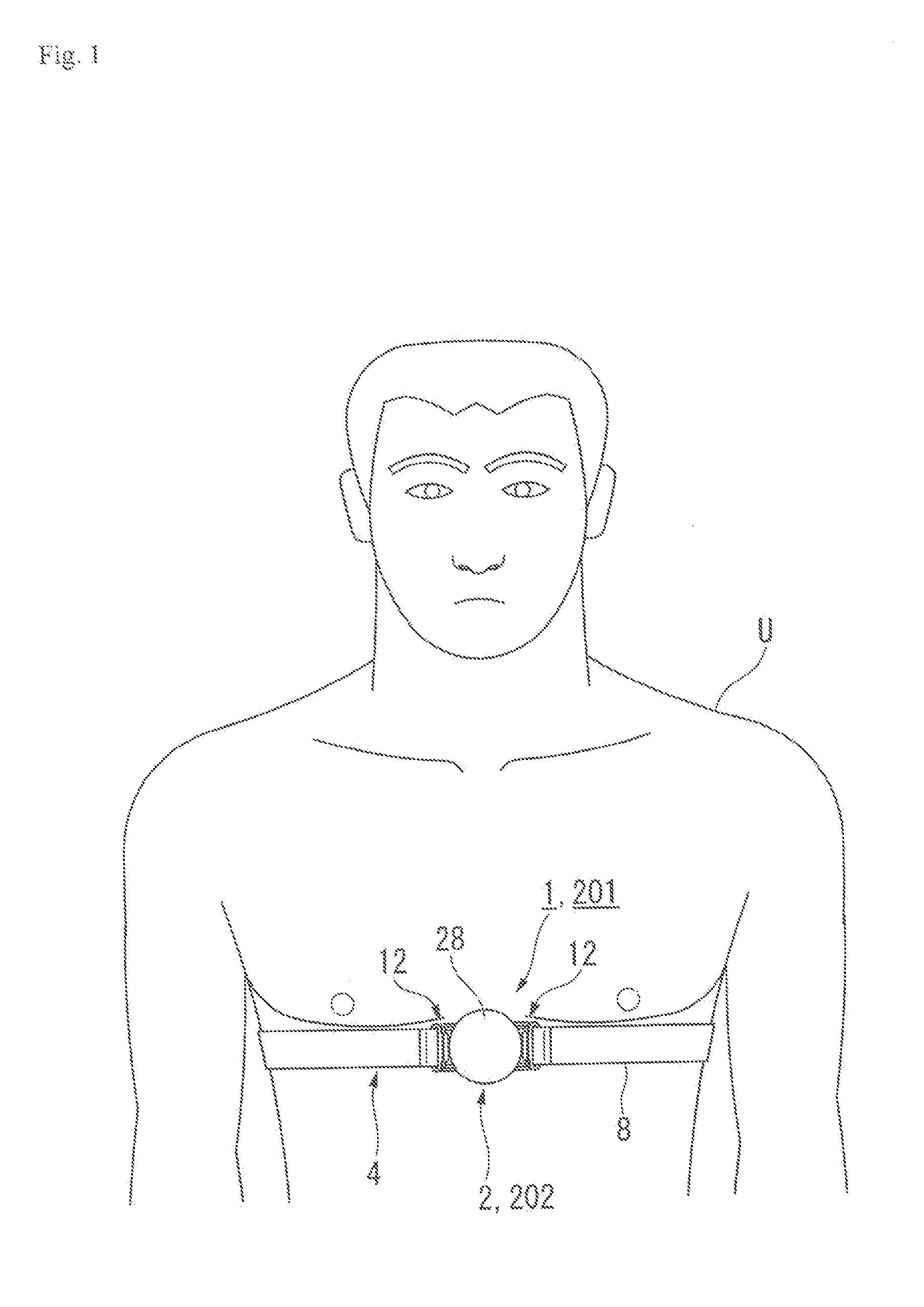
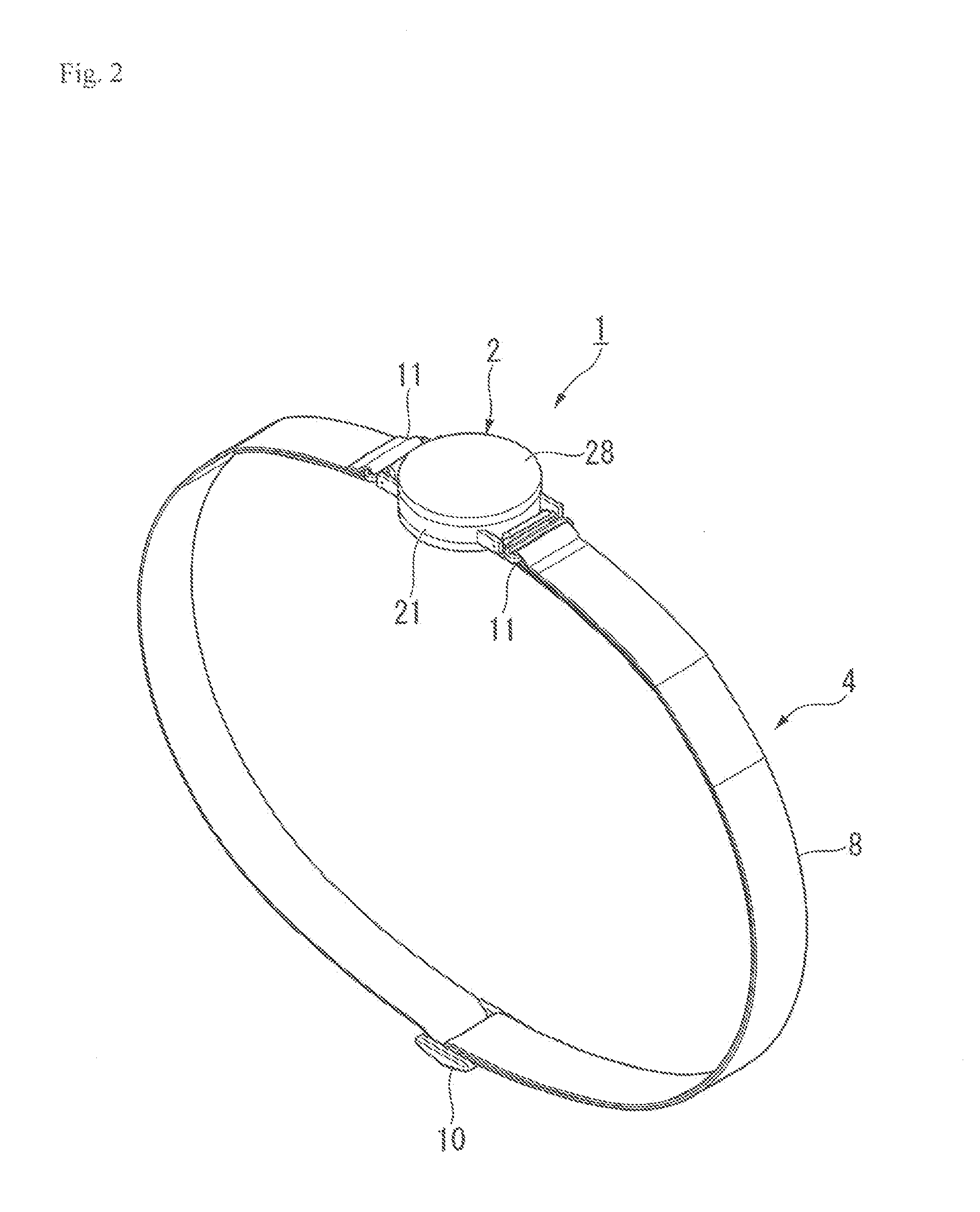
[0039]FIG. 1 is an explanatory diagram illustrating a state where a heartbeat measurement device 1 which is a biological information detection device according to the present invention is installed on a user U, FIG. 2 is a perspective view illustrating the heartbeat measurement device 1, and FIG. 3 is an exploded perspective view of a portion of the heartbeat measurement device 1.

[0040]Meanwhile, in the following description, the side which comes into contact with the user U in a state where the heartbeat measurement device 1 is mounted by the user U is expressed as the back side, and the surface on the side opposite to this back side and the side directed to the outside is expressed as the front side, and the like.

[0041]As shown in FIGS. 1 to 3, the heartbeat measurement device 1 is mounted to the chest which is a biological surface of the user U to d...

first modified example of first embodiment

[0087]FIG. 10 is a cross-sectional view illustrating a main body portion 2′ according to a first modified example of the first embodiment. Meanwhile, the same components as those of the above-mentioned first embodiment are designated by the same reference signs, and a description thereof will be omitted (the same is true of the following modified example and the Embodiment).

[0088]As shown in the came drawing, in the first modified example of the first embodiment, the main body portion 2′ includes a lower case 21′ and an upper case 28′. The following basic configuration of the modified example is the same as that of the above-mentioned first embodiment (the same is true of the following second modified example of the first embodiment): the detection circuit board 27 is provided within the lower case 21′; the electrodes 6a and 6b constituting the heartbeat detection portion 3 are integrally connected to the lower case 21′, and the like.

[0089]Herein, a concave portion 32 receiving an e...

second modified example of first embodiment

[0097]FIG. 11 is a cross-sectional view illustrating the main body portion 2′ according to a second modified example of the first embodiment.

[0098]As shown in the same drawing, the electrodes 6a and 6b are formed thick by the thickness equivalent to that of the fined reinforcing plate 35 according to the above-mentioned first embodiment. The fixed reinforcing plate 35′ according to the second modified example of the first embodiment is insert-molded on the electrodes 6a and 6b.

[0099]The fixed reinforcing plate 35′ includes a first plate portion 61 disposed at a position corresponding to the concave portion 34 of the lower case 21′ and a second plate portion 62 disposed at a position corresponding to the concave portion 52 of the lower case 21′.

[0100]The first plate portion 61 is buried in the electrodes 6a and 6b. In addition, she second plate portion 62 is disposed so as to be exposed to the back side of the electrodes 6a and 6b. Further, the thickness of the second plate portion ...


PUM


Abstract

A biological information detection device includes a main body portion, a heartbeat detection portion, forced integrally with the main, body portion, which has electrodes that come into contact with a biological surface, and a fixing band, detachably provided to the main body portion, which mounts the main body portion and the heartbeat detection portion to a user. A sealing portion for securing sealing of an electrical connection portion is provided in the periphery of the electrical connection portion that electrically connects the main body portion to the electrodes of the heartbeat detection portion.

Description

BACKGROUND OF THE INVENTION [0001]1. Field of the Invention[0002]The present invention relates to a biological information detection device that detects a biological signal by installing an electrode on the biological surface of the human body.[0003]2. Background Art[0004]Among these kinds of biological information detection devices, there is, For example, a device that detects an electro-cardiac signal generated in association with a heartbeat, and measures a heart rate from the biological surface. As such a biological information detection device, there is, for example, a device which includes a main body portion having a detection circuit board and the like built-in, and a strap which mounts the main body portion to the human body, the strap being provided with a pair of electrodes. The main body portion and the strap are provided with an electrical connection portion for electrically connecting a detection circuit board of the main body portion to an electrode of the strap.[0005...

Claims


Application Information

Patent Timeline
IPC IPC(8): A61B5/0408
CPCA61B5/0408A61B5/0006A61B5/02438A61B5/6823A61B5/6831A61B5/0245A61B5/25
Inventor OKUDA, HIDEKIKATO, TERUOTERASAWA, DAIKANEKO, TAKAHIROKAWAMATA, HIROSHIOMORI, NOBUKAZUKOSHOJI, HIDEAKI
Owner SEIKO INSTR INC
Features
  • Generate Ideas
  • Intellectual Property
  • Life Sciences
  • Materials
  • Tech Scout
  • Unparalleled Data Quality
  • Higher Quality Content
  • 60% Fewer Hallucinations
Learn More