Control for Compressor Unloading System

a compressor and unloading technology, applied in the direction of machines/engines, positive displacement liquid engines, lighting and heating apparatus, etc., can solve the problems of reducing the overall system efficiency, reducing the efficiency of the overall system, so as to reduce or stop the flow

Active Publication Date: 2013-06-06
BITZER US
View PDF6 Cites 25 Cited by
  • Summary
  • Abstract
  • Description
  • Claims
  • Application Information

AI Technical Summary

Benefits of technology

[0006]In one aspect, embodiments of the invention provide a variable-capacity compressor that includes a housing having an inlet for receipt of refrigerant and an outlet for return of refrigerant, and a plurality of compressing elements contained in the housing between the inlet and the outlet. The compressor further includes at least one valve having an electrical control. Each valve is dedicated to selected compressing elements that are fewer than all of the plurality of compressing elements. Also, each valve is movable between a first state in which the at least one valve is open to communicate refrigerant flow to the compressing elements, and a second closed state in which the at least one valve is closed to reduce or stop flow to the compressing elements relative to the first open state. The unloading controller is programmed to implement an operational modulation mode to cycle the at least one valve between on and off states to provide a portion of capacity represented by the at least one valve's corresponding compressing elements. In a particular embodiment of the invention, the unloading controller is programmed to provide a minimum delay time between transitions between the first and second states, but no maximum dwell time between transitions. In a more particular embodiment, the minimum delay time ranges from 5 to 40 seconds.

Problems solved by technology

However, most refrigeration systems operate at peak load for only a few hours out of the year and spend most of the time operating at a load point less then the peak design load.
However, with this method of compressor unloading, the energy expended to compress the refrigerant is wasted each cycle that the refrigerant is recirculated back to the suction side of the compressor, thus reducing overall system efficiency.
As a result, maintaining and operating the types of conventional refrigeration systems described above can be costly.

Method used


Image

  • Control for Compressor Unloading System
  • Control for Compressor Unloading System
  • Control for Compressor Unloading System

Examples


Embodiment Construction

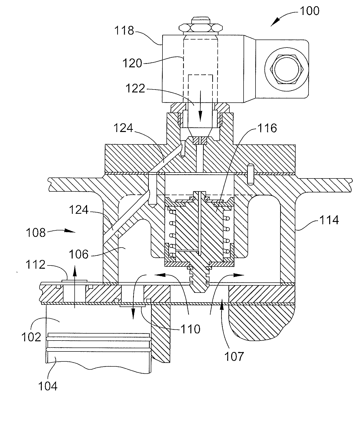
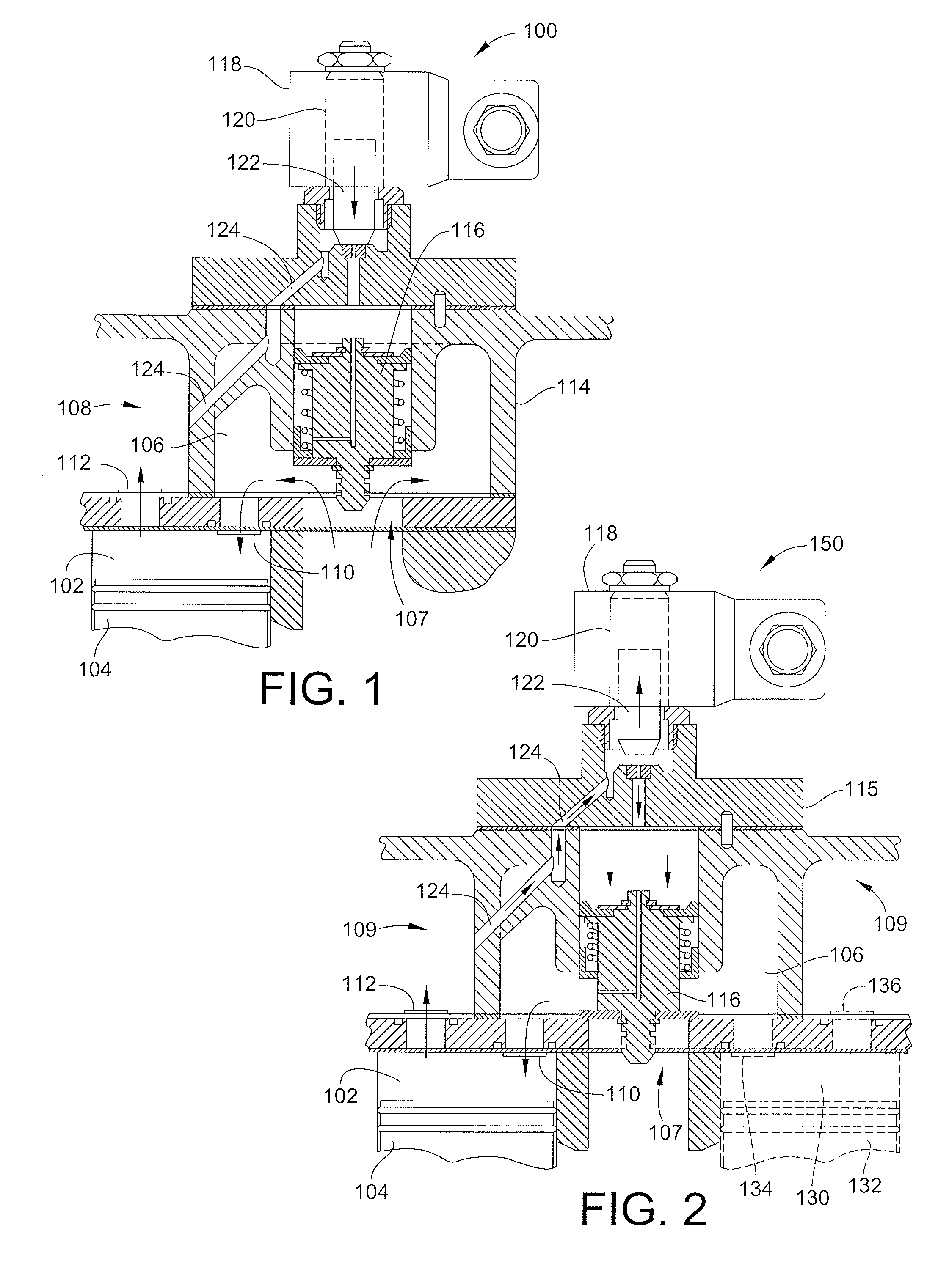
[0035]The following detailed description describes embodiments of the invention as applied in a refrigeration system. However, one of ordinary skill in the art will recognize that the invention is not necessarily limited to refrigeration systems. Embodiments of the invention may also find use in other systems where compressors are used to supply a flow of compressed gas.

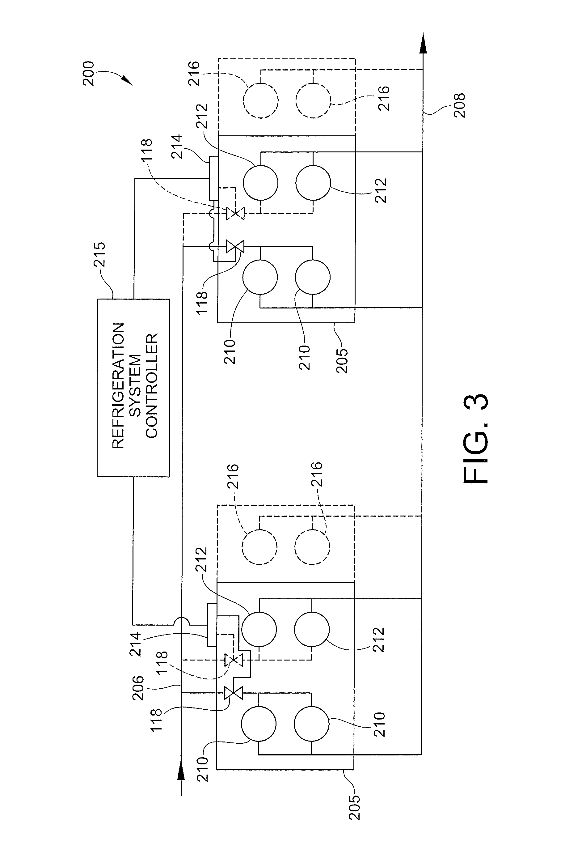
[0036]As will be shown below, the demand placed on a refrigeration system may vary with the load placed on the refrigeration system. One way the efficiency of refrigeration systems is increased involves modulating the capacity of the refrigeration system, that is, adjusting the output of the refrigeration system in response to changes in demand. Embodiments of the present invention provide a system for modulating the capacity of a refrigeration system which can be implemented without customized components, and further can be used to retrofit existing refrigeration systems to reduce the cost of operating these systems...


PUM


Abstract

A variable-capacity compressor that includes a housing having an inlet for receipt of refrigerant and an outlet for return of refrigerant, and a plurality of compressing elements contained in the housing between the inlet and the outlet. The variable capacity compressor includes a valve having an electrical control. The valve is dedicated to fewer than all of the compressing elements. The valve is movable between a first state which communicates refrigerant flow to the compressing elements, and a second state that reduces or stops flow to the compressing elements. In an embodiment of the invention, an unloading controller has an operational modulation mode that includes cycling the valve between on and off states to provide a portion of compressor capacity. The unloading controller is further programmed to provide a minimum delay time between transitions between the first and second states, but no maximum dwell time between transitions.

Description

CROSS-REFERENCE TO RELATED PATENT APPLICATIONS[0001]This patent application claims the benefit of U.S. Provisional Patent Application No. 61 / 567,174 filed Dec. 6, 2011, the entire teachings and disclosure of which are incorporated herein by reference thereto.FIELD OF THE INVENTION[0002]This invention generally relates to system for modulating the capacity of a compressor or group of compressors.BACKGROUND OF THE INVENTION[0003]Refrigeration systems, particularly commercial and industrial refrigeration systems, may have a single compressor though these systems often include a number of refrigerant compressors. Typically, there are enough compressors to accommodate the anticipated peak load to be placed on the refrigeration system. However, most refrigeration systems operate at peak load for only a few hours out of the year and spend most of the time operating at a load point less then the peak design load. As such, it is desirable to be able to modulate the capacity of the refrigerat...

Claims


Application Information

Patent Timeline
Patent Type & Authority Applications(United States)
IPC IPC(8): F04B49/00F25B1/02
CPCF04B49/00F25B1/02F04B27/1009F04B27/24F04B39/10F25B2600/23F04B49/06F25B49/022F25B2400/075F25B2600/0262F04B49/03Y10T137/85986F04B39/08
Inventor NARES, TERRYSANCHEZ, JOSEPH DUMONTNARREAU, PETER PAUL
Owner BITZER US
Why Eureka
Try Eureka