

Rope braking apparatus
- Summary
- Abstract
- Description
- Claims
- Application Information
AI Technical Summary
Benefits of technology
Problems solved by technology
Method used
Image

Examples
Embodiment Construction
[0025]Hereinafter, embodiments of the present invention will be described in detail with reference to the accompanying drawings so that those skilled in the art pertaining to the present invention can easily practice it. However, the present invention can be implemented in a number of different forms, and is not limited to the embodiments described below. The same components are given the same reference numerals throughout the description.
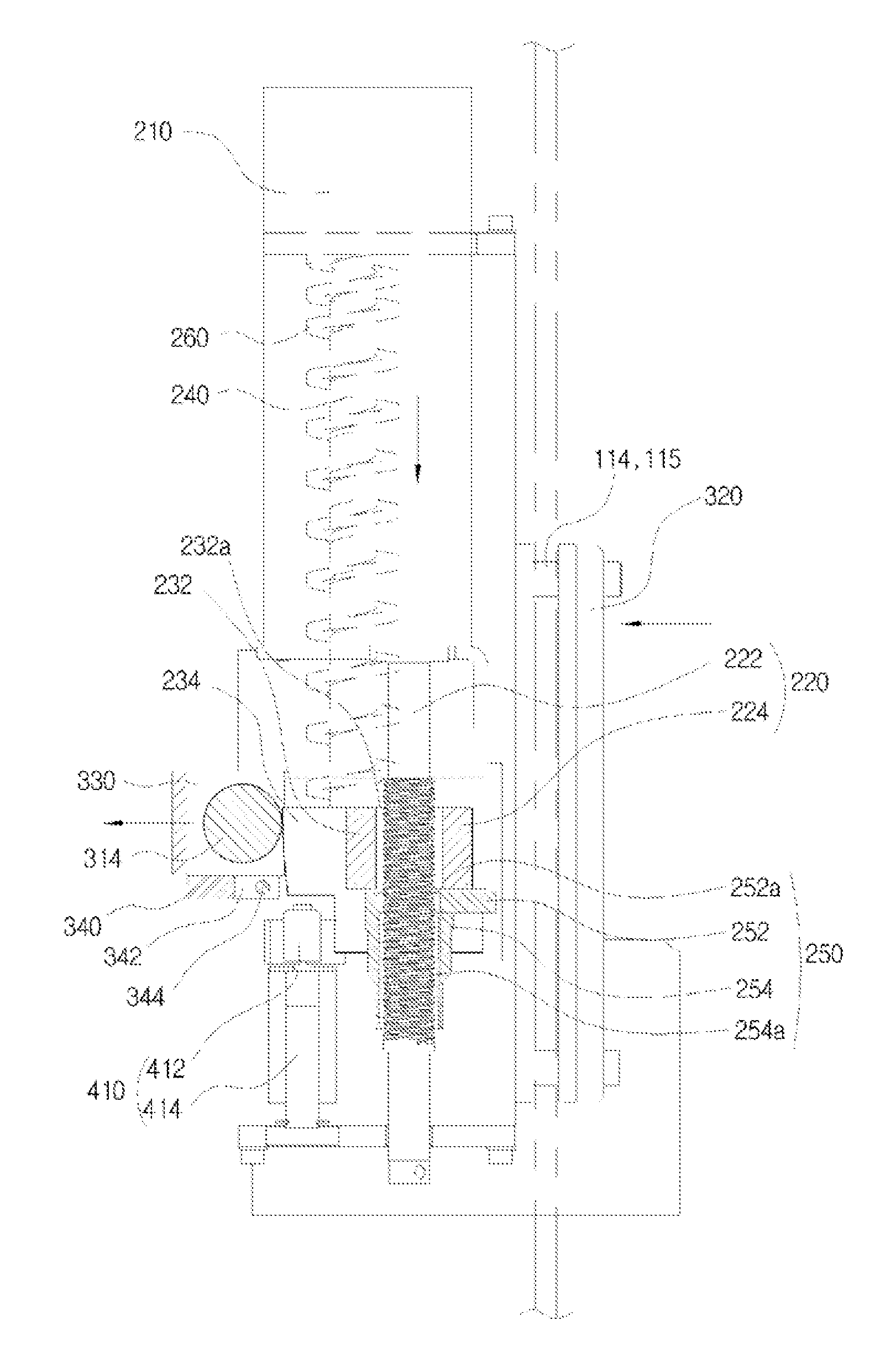
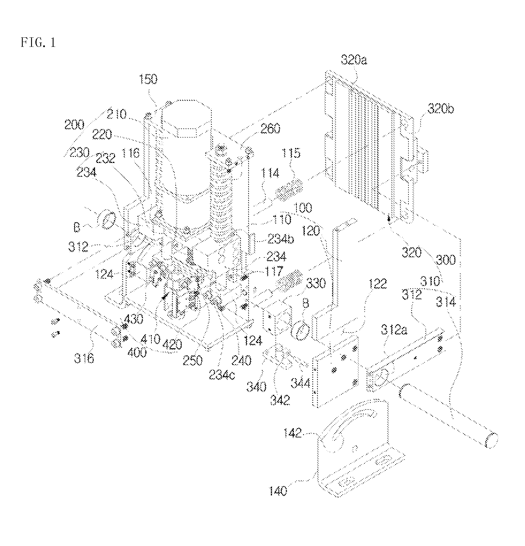
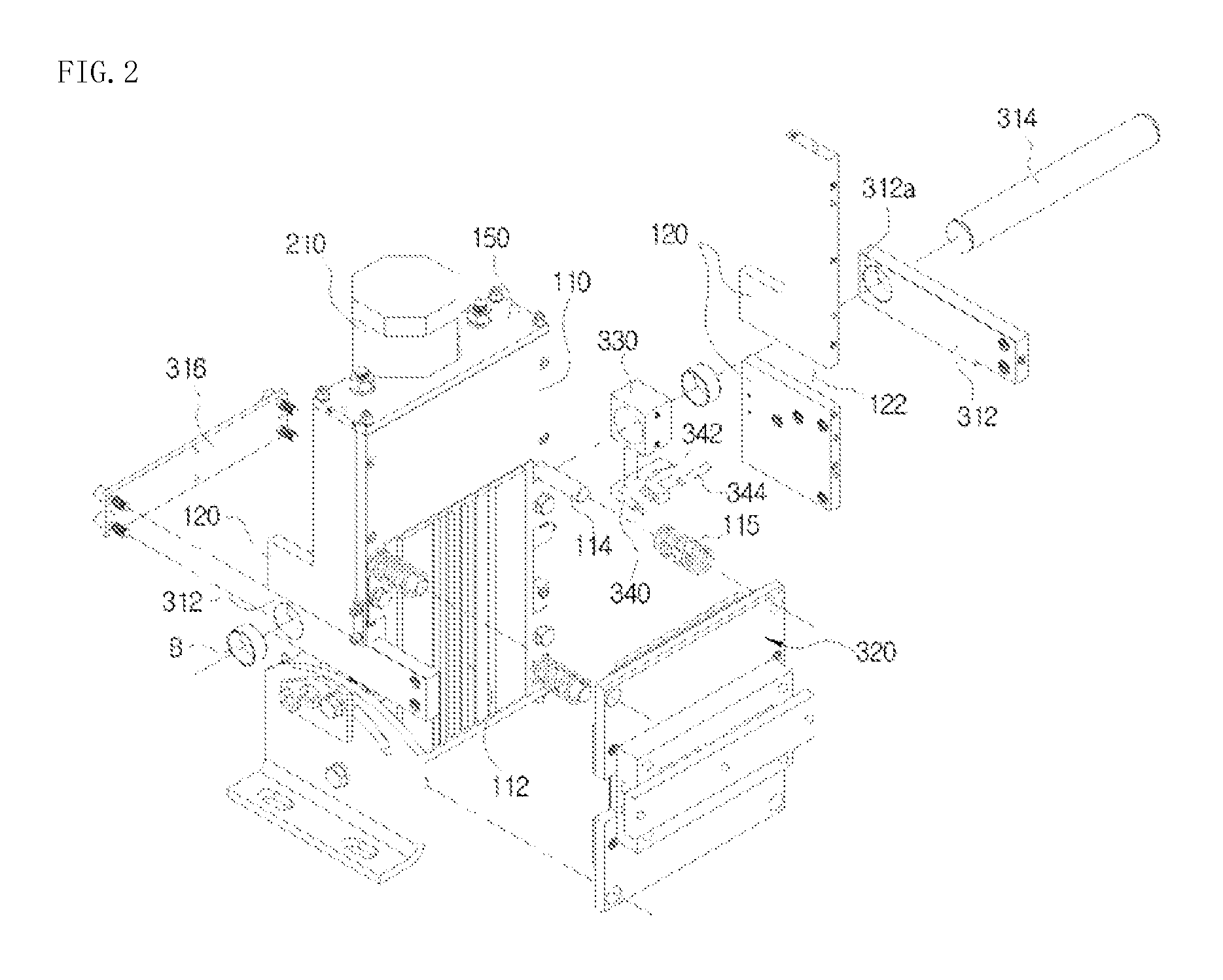
[0026]The rope braking apparatus according to the present invention includes, as illustrated in FIGS. 1 to 7, an installation body 100, a driving unit 200, a pressurization unit 300, and a movement control unit 400.
[0027]The installation body 100 serves as an overall case according to the present invention, which has an overall shape of a quadrangular box, and, more specifically, has lateral plates 120 installed on both sides of a rear plate 110 so that an installation space 130 is defined therein.
[0028]Both lateral plates 120 include fixing frames...
PUM
 Abstract
Description
Claims
Application Information