Window installation assembly and method to install windows

a technology for installing windows and windows, applied in the field of window frame clips, can solve the problems of complex installation process, inability to properly insert glass, and extensive labor required by the existing method of window installation,

Inactive Publication Date: 2013-06-13
STEIN JR WILLIAM E
View PDF2 Cites 14 Cited by
  • Summary
  • Abstract
  • Description
  • Claims
  • Application Information

AI Technical Summary

Benefits of technology

[0009]It is an aspect of the present inventive concept to provide for an improvement in window installation.

Problems solved by technology

The existing method of window installation requires extensive skilled labor to install prefabricated frame pieces into existing window openings.
The frame must be level and plumb to the building or the glass cannot be inserted properly.
The material of the building structure can complicate the installation process.
Hard structural materials require a large amount of force to penetrate with a fastener such as a screw or nail.
This forceful penetration causes problems including causing the frame to move out of alignment.
Further, use of a drill can cause debris from the window frame or building material to be created that then falls into the window glass pocket that will need to be cleaned out before glass is installed, prolonging the installation.
In addition to the cleanup of the debris from the window frame, the forceful attachment of the window frame to the building can cause the frame pieces to shift as they are merely held in by shims and friction fit prior to the attachment.
Thus, care and attention is required and owing to the size of the frame pieces that must be attached and the hardness of the material it is being attached to, attaching the window frame to the building requires extensive onsite effort.
It is the transition from shims to permanent attachment of the window frame to the building structure that is time consuming and unreliable.
The use of ad hoc adjustments requires additional skill and time, and can provide a less aesthetically pleasing finished window if not accomplished within fine tolerances.
If leveling is not achieved, the window as visible from the exterior and interior of the building will not appear aesthetically pleasing and may not match the other windows of the building.
Variations in the dimensions of the window installation may lead to water leakage and associated water damage.
Several attempts have been made to simplify the frame attachment and window installation process, but none have been successful in reducing the amount of time and skill necessary for the job to be completed properly.
However, this clip piece does not allow the user to adjust the level of the frame in relation to the building.
It is not adjustable nor does it provide a height adjustment.
It does not provide a centering function to ensure that the window is plumb relative to the sill.
The use of the Kirk device does not increase the available tolerance on a track installation.
The Kirk device does not reduce the requirement of skilled workers to install the window frame properly.

Method used


Image

  • Window installation assembly and method to install windows
  • Window installation assembly and method to install windows
  • Window installation assembly and method to install windows

Examples


Embodiment Construction

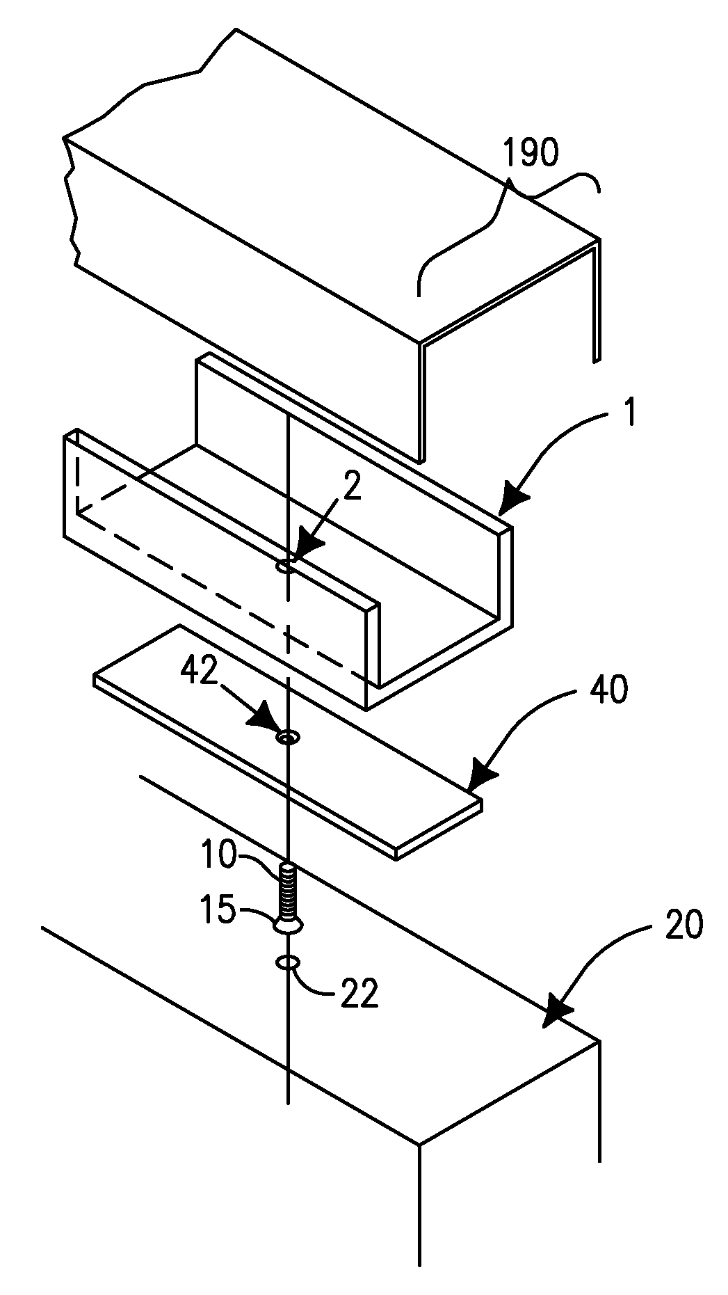
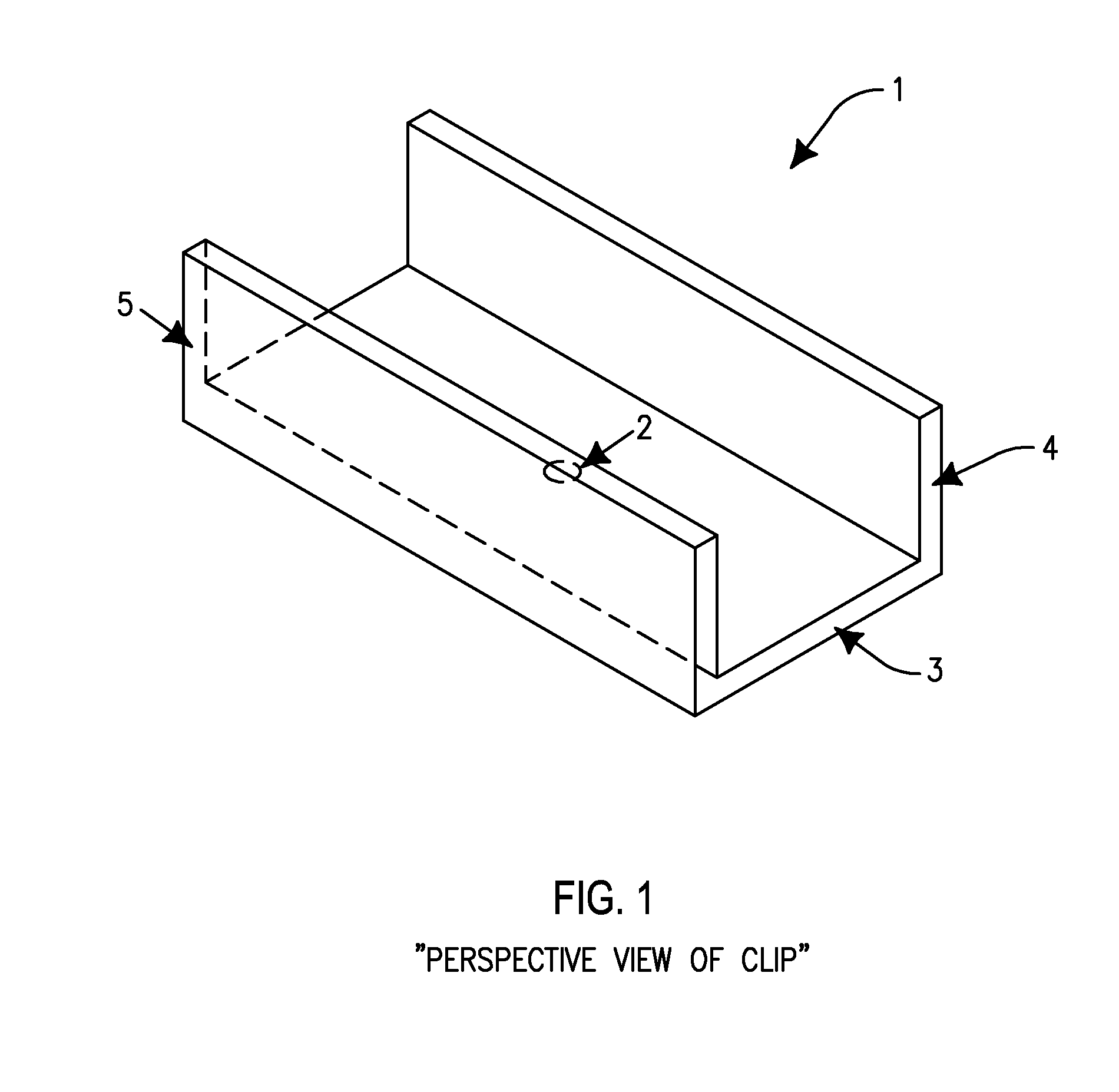
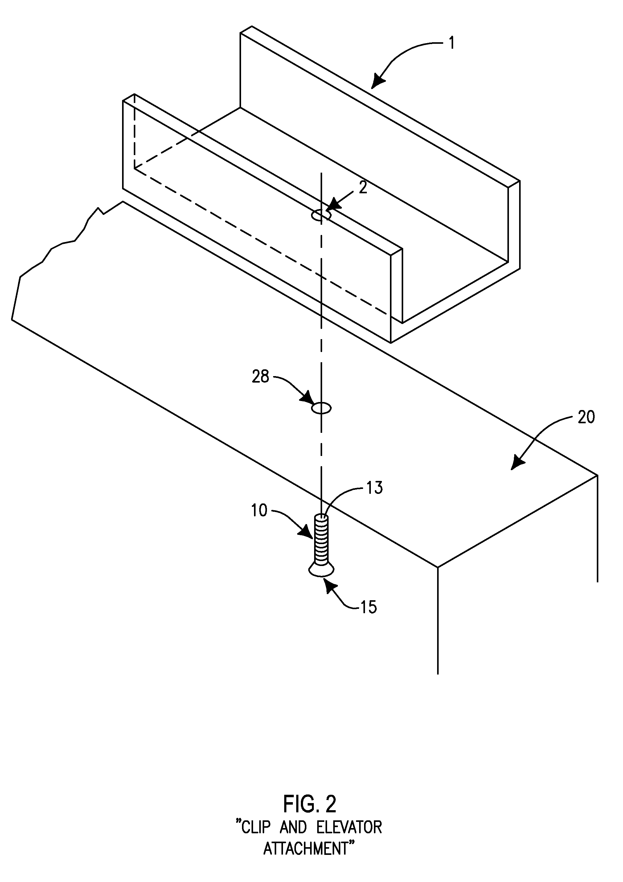
[0026]This description of the exemplary embodiments is intended to be read in connection with the accompanying drawings, which are to be considered part of the entire written description. In the description, relative terms such as “lower,”“upper,”“horizontal,”“vertical,”, “above,”“below,”“up,”“down,”“top” and “bottom” as well as derivative thereof (e.g., “horizontally,”“downwardly,”“upwardly,” etc.) should be construed to refer to the orientation as then described or as shown in the drawing under discussion. These relative terms are for convenience of description and do not require that the apparatus be constructed or operated in a particular orientation. Terms concerning attachments, coupling and the like, such as “connected” and “interconnected,” refer to a relationship wherein structures are secured or attached to one another either directly or indirectly through intervening structures, as well as both movable or rigid attachments or relationships, unless expressly described othe...


PUM


Abstract

A device is provided to improve the installation of a window frame within a window opening comprising a clip, a track, a base plate, and an elevator attachment. The device of the invention and the method of utilizing the device improve the efficiency and effectiveness of current installation methods by providing rapid installation of a frame that is centered and true and additionally vertically adjustable via an elevator attachment.

Description

FIELD OF THE INVENTION[0001]The present inventive concept provides a window frame clip for assisting the installation of windows in a building, and a method for installing the window frame clip into a track. The clip and track reduce the amount of skilled labor required to correctly install window framing and for window glass installation.BACKGROUND[0002]The present inventive concept relates to a device and method to install windows in the wall of a building. For large windows, the frame is typically prefabricated at another location and erected and attached to the structure onsite. The metal forming the frames can be extruded in mass quantities, creating numerous frame pieces at one time, reducing the manufacturing costs. Installation is performed at the job site where a sill is installed in the interior of the rough window opening and then the frame pieces are installed to meet the sill and the rough window opening. After the frame is attached to the building in the rough opening,...

Claims


Application Information

Patent Timeline
Patent Type & Authority Applications(United States)
IPC IPC(8): E06B1/60E06B1/56E06B1/00E06B1/36
CPCE06B1/6076E06B1/02
Inventor STEIN, JR., WILLIAM E.
Owner STEIN JR WILLIAM E
Why Eureka
Try Eureka