Processes and systems for drilling a borehole

a technology for drilling and drilling processes, applied in the direction of drilling pipes, borehole/well accessories, surveying, etc., can solve the problems of difficult drilling of boreholes, and achieve the effect of reducing the amount of energy expended and not sacrificing the penetration ra

Inactive Publication Date: 2013-06-13
DISANTIS JOSEPH R
View PDF2 Cites 38 Cited by
  • Summary
  • Abstract
  • Description
  • Claims
  • Application Information

AI Technical Summary

Benefits of technology

[0015]In another characterization of the present invention, a process is provided for drilling a borehole comprising obtaining real-time data necessary to determine a gravitational energy term, a torsional energy term, a hydraulic energy term and a hydromechanical specific energy which is the sum of the gravitational energy term, the torsional energy term and the hydraulic energy term and determining values for these energy terms. The determined values for each of the gravitational energy term, the torsional energy term and the hydraulic energy term may be compared against corresponding setpoints for each of the gravitational energy term, the torsional energy term and the hydraulic energy term. At least one drilling parameter may be automatically adjusted based upon the comparison to thereby reduce the amount of energy expended to destroy and remove a given unit volume of rock without sacrificing the rate of penetration.

Problems solved by technology

Historically, drilling a borehole has proved to be difficult since an operator of the drilling rig typically does not have immediate access to, or the ability to make decisions based upon detailed rock mechanical properties and must rely on knowledge and experience to change those drilling parameters that are adjustable.

Method used


Image

  • Processes and systems for drilling a borehole
  • Processes and systems for drilling a borehole
  • Processes and systems for drilling a borehole

Examples


Embodiment Construction

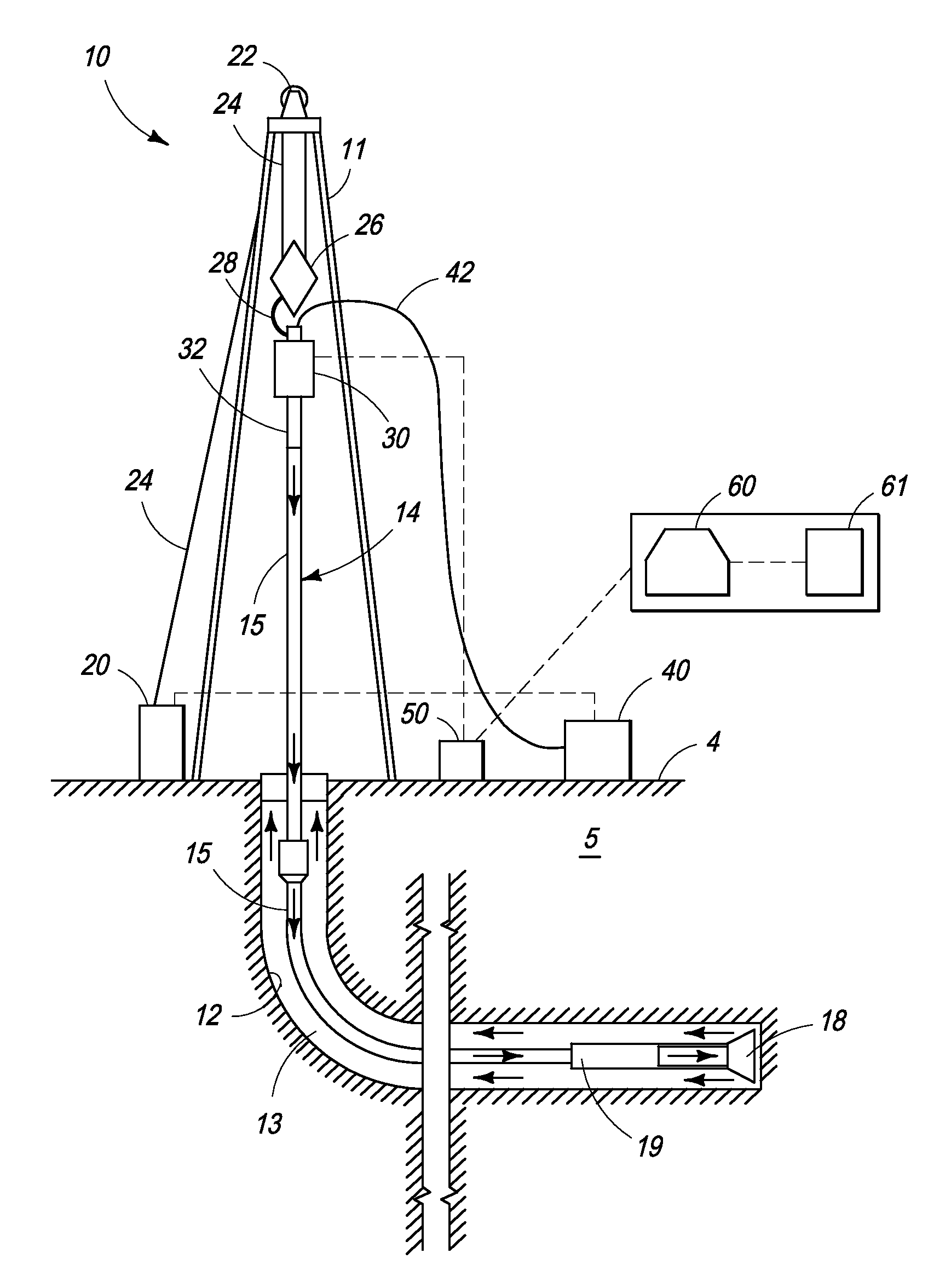
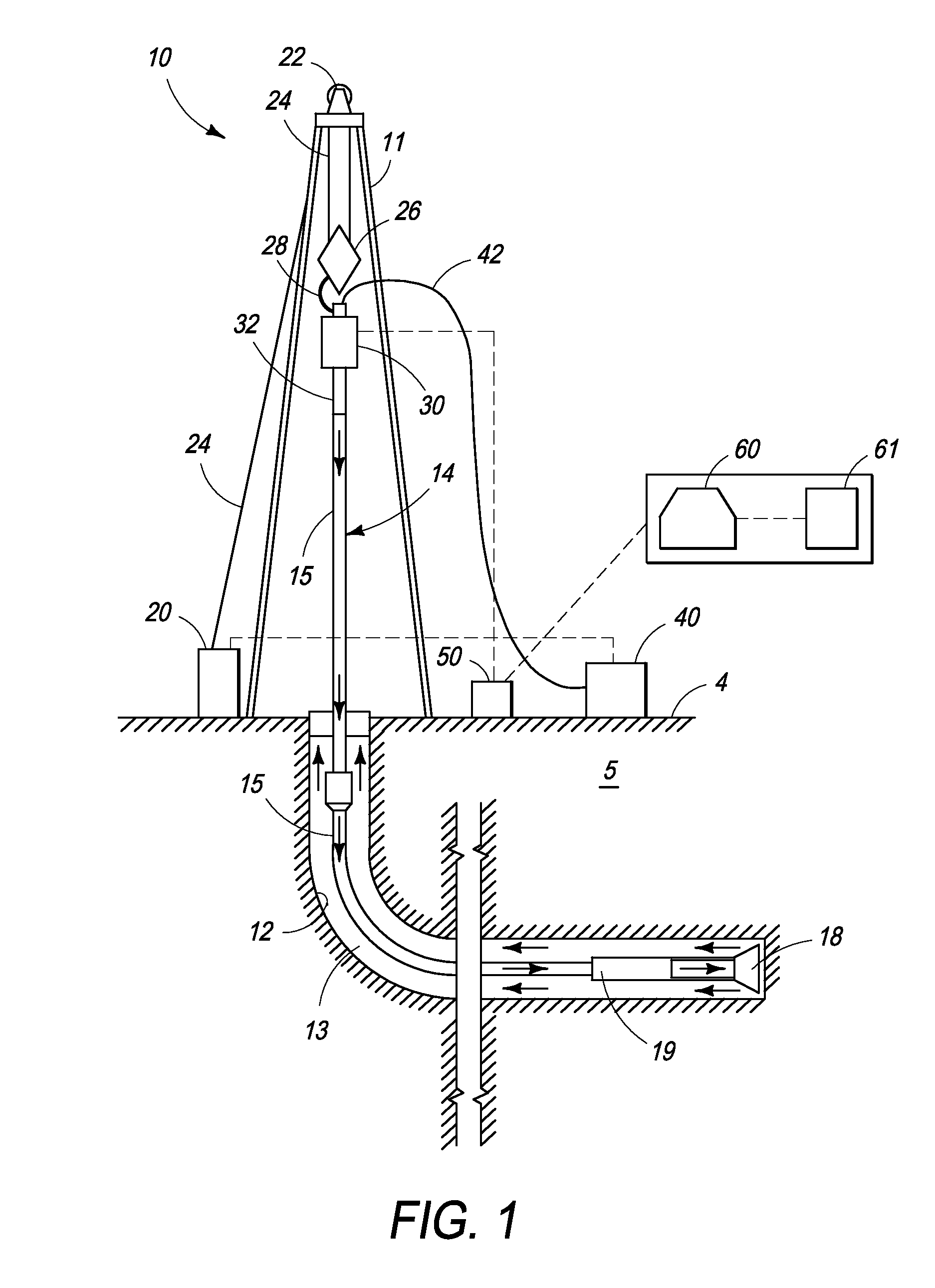
[0026]The processes and systems of the present invention may be practiced and deployed in a borehole which may be formed by any suitable means, such as by a rotary drill string, as will be evident to a skilled artisan. As used throughout this description, the term “borehole” is synonymous with wellbore and means the open hole or uncased portion of a subterranean well including the rock face which bounds the drilled hole. A “drill string” may be made up of tubulars secured together by any suitable means, such as mating threads, and a drill bit secured at or near one end of the drill string. The borehole may extend from the surface of the earth, including land, a sea bed or ocean platform, and may penetrate one or more environs of interest. As used throughout this description, the terms “environ” and “environs” refers to one or more subterranean areas, zones, horizons and / or formations that may contain hydrocarbons. The borehole may have any suitable subterranean configuration, such a...


PUM


Abstract

Processes and systems for drilling a borehole wherein a gravitational energy term, a torsional energy term, a hydraulic energy term and a hydromechanical specific energy which is the sum thereof may be determined using real-time data and compared against corresponding setpoints. The hydraulic energy term may include a hydraulic energy reduction factor so as to account for the distance between the fluid nozzle of the drill bit and the rock and may include the kinematic viscosity of drilling fluid. One or more drilling parameters, such as weight on bit, revolutions per minute, drilling fluid flow rate, or combinations thereof, may be adjusted based upon such comparison to approximate the least amount of energy required to destroy and remove a given unit volume of rock. The setpoints may be changed manually or automatically at the direction of the user.

Description

BACKGROUND OF THE INVENTION[0001]1. Field of the Invention[0002]The present invention relates to processes and systems for drilling a borehole, and more particularly, to processes and systems for drilling a borehole wherein the real-time specific drilling energies applied to the borehole are continually controlled to efficiently approximate and deliver the least amount of energy required to destroy and remove a given unit volume of rock without sacrificing rate of penetration.[0003]2. Description of Related Art[0004]In the production of fluid, from subterranean environs, a borehole may be drilled in a generally vertical, deviated or horizontal orientation so as to penetrate one or more subterranean locations of interest. Typically, a borehole may be drilled by using drill string which may be made up of tubulars secured together by any suitable means, such as mating threads, and a drill bit secured at or near one end of the drill string. Drilling operations may also include other equ...

Claims


Application Information

Patent Timeline
Patent Type & Authority Applications(United States)
IPC IPC(8): E21B44/00E21B7/00
CPCE21B44/00E21B44/02E21B7/00
Inventor DISANTIS, JOSEPH R.
Owner DISANTIS JOSEPH R
Why Eureka
Try Eureka