Cluster-type fluid-conducting pipe connecting device

a fluid-conducting pipe and connecting device technology, applied in the direction of pipe joints, other medical devices, adjustable joints, etc., can solve the problems of increasing the number of pneumatic/hydraulic pipelines, bedridden patients, and increasing the number of patients, so as to simplify the arrangement of fluid-conducting pipes

Inactive Publication Date: 2013-06-13
CAREMED SUPPLY
View PDF9 Cites 17 Cited by
  • Summary
  • Abstract
  • Description
  • Claims
  • Application Information

AI Technical Summary

Benefits of technology

[0005]A primary object of the present invention is to provide a cluster-type fluid-conducting pipe connecting device that enables convenient and firm connection of a large number of fluid-conducting pipes to, for example, a medical bed at one time, so as to simplify the arrangement and laying of the fluid-conducting pipes.
[0014]With the above arrangements, the present invention allows a user to connect multiple fluid-conducting pipes to an apparatus, such as a medical bed, at one time to largely simplify the arrangement of fluid-conducting pipes.

Problems solved by technology

Many patients are bedridden due to illness or injure.
Since a bedridden patient can not move freely on bed, he or she tends to gradually lose his or her muscular functions.
Moreover, being unable to freely turn on bed, bedsores tend to form on some specific areas of the bedridden patient's body that are frequently subjected to pressure while the patient is lying in bed.
However, the number of pneumatic / hydraulic pipelines and the difficulty in arranging and laying these pipelines will largely increase when the medical beds have quite complicated design and structure.
However, the currently available fluid-conducting pipe connection apparently fails to effectively achieve the above requirements.

Method used


Image

  • Cluster-type fluid-conducting pipe connecting device
  • Cluster-type fluid-conducting pipe connecting device
  • Cluster-type fluid-conducting pipe connecting device

Examples


first embodiment

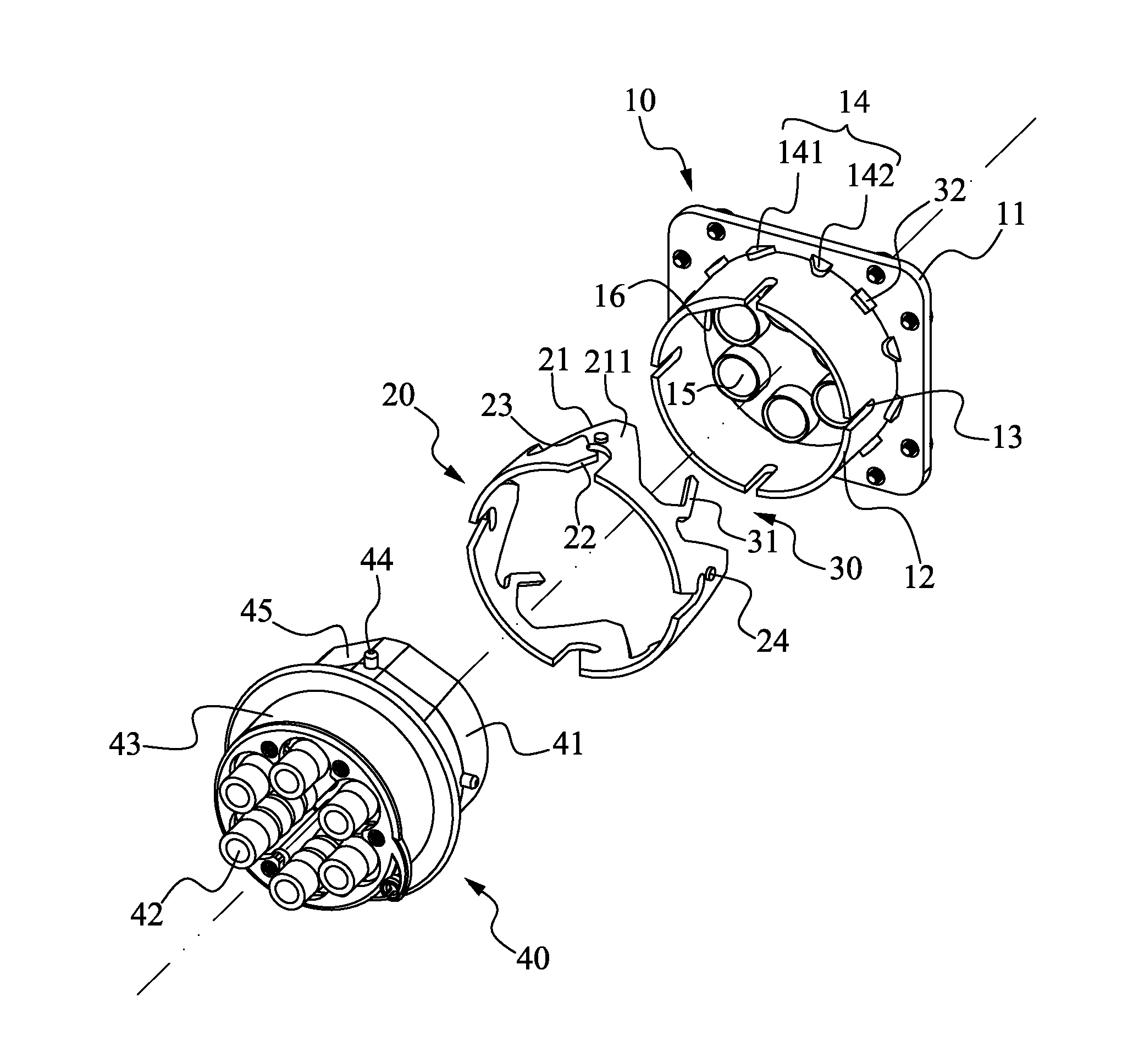
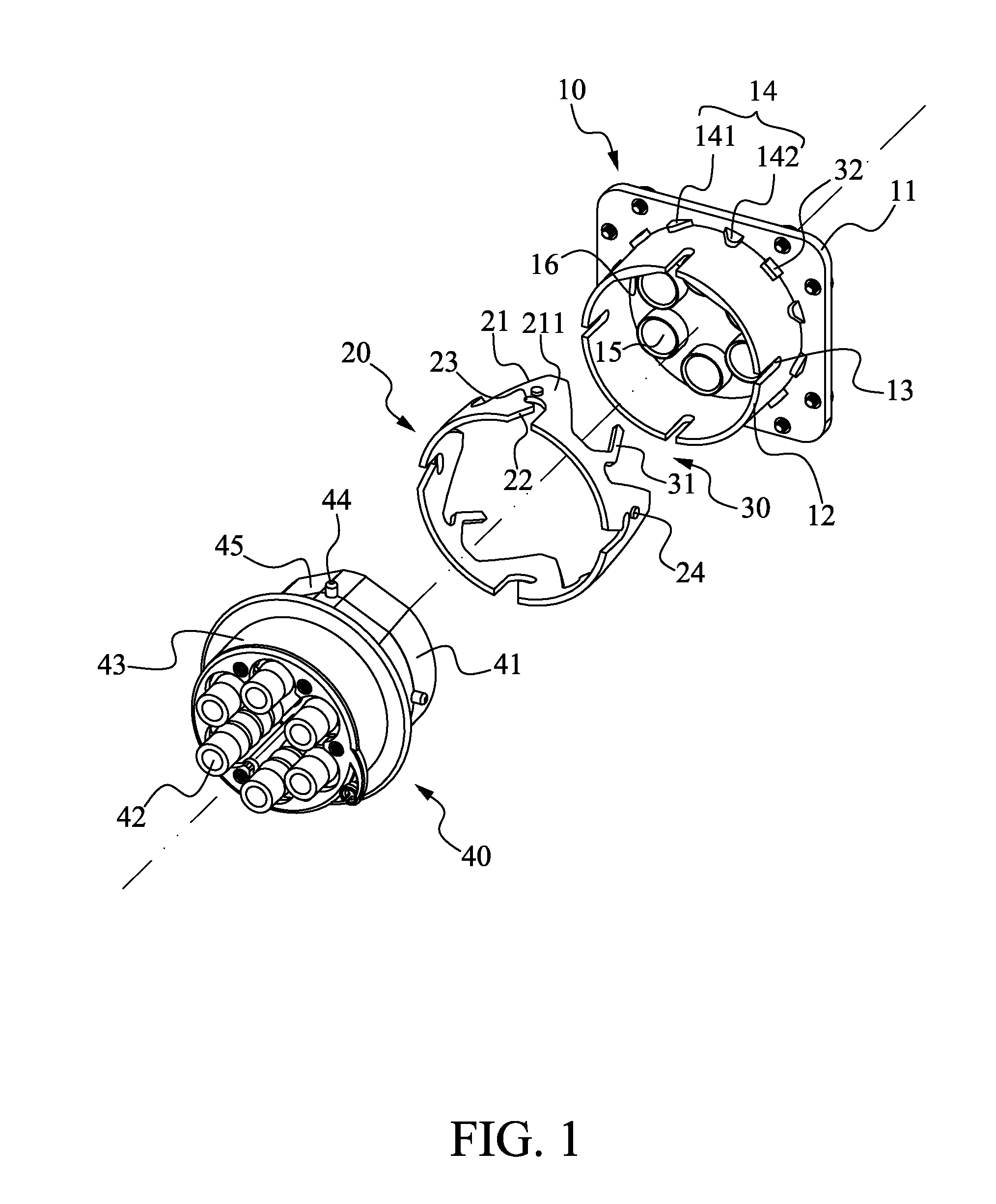
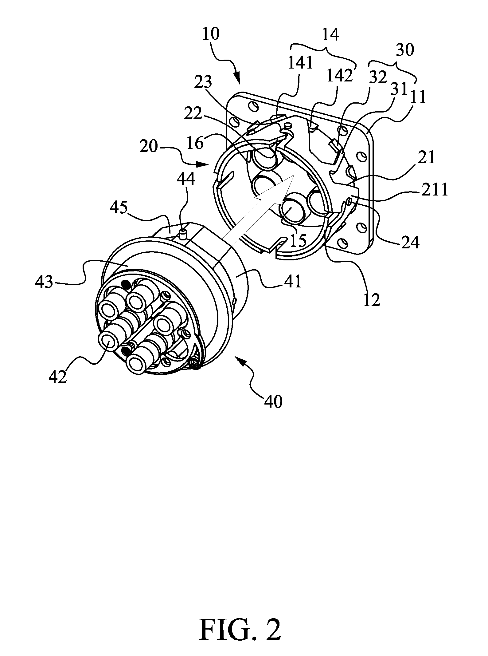
[0026]The reset structure 30 is provided on the retaining ring 20 for automatically resetting the retaining ring 20 to a closed position when the retaining ring 20 is released from any external force applied thereto. In the illustrated first embodiment, the reset structure 30 includes at least one elastic arm 31 and a mating stopper 32. The elastic arm 31 is rearwardly extended from a rear end of the retaining ring 20, and the stopper 32 is arranged at the rear end of the tubular wall 12 of the base section 10 with the elastic arm 31 abutting on the mating stopper 32. When the retaining ring 20 is fitted on the base section 10, the elastic arm 31 is firmly abutted against the mating stopper 32 to produce a force for the retaining ring 20 to rotate clockwise, so that the retaining ring 20 is pushed to the closed position.

[0027]The connector 40 has an end configured as a rearward extended plug section 41 for inserting into the tubular wall 12 of the base section 10, and an axially opp...

second embodiment

[0032]In the illustrated second embodiment, the ring-shaped cover 50 is provided on an inner surface with a plurality of sliding slots 54, and the retaining ring 20 is correspondingly provided on an outer surface with a plurality of protrusions 24 for engaging with the sliding slots 54. Therefore, the ring-shaped cover 50 externally fitted around the retaining ring 20 can bring the latter to rotate synchronously, and a user may conveniently turn the ring-shaped cover 50 to move the retaining ring 20 to its open position. Further, the ring-shaped cover 50 is provided on an outer surface with a plurality of anti-slip flutes for the user to turn the ring-shaped cover 50 easily.

[0033]In summary, the cluster-type fluid-conducting pipe connecting device according to the present invention includes a base section, a retaining ring fitted around a front tubular wall of the base section, a reset structure, and a connector. The retaining ring and the tubular wall are correspondingly provided a...


PUM


Abstract

A cluster-type fluid-conducting pipe connecting device includes a base section; a retaining ring fitted to a front of the base section and turnable from a closed position to an open position; the retaining ring and the base section being correspondingly provided at a front end with fixing slots and connection slots, respectively, and a sideward locating slot being formed at a rear end of each fixing slot; a reset structure enabling the retaining ring to automatically return from the open position to the closed position; and a connector having a forward pipe engaging section for fluid-conducting pipes to connect thereto, and a rearward plug section for inserting into the base section and externally provided with stubs that slide into the connection and fixing slots while the retaining ring is in the open position and are locked in the locating slots while the retaining ring is in the closed position.

Description

FIELD OF THE INVENTION[0001]The present invention relates to a fluid-conducting pipe connecting device, and more particularly to a cluster-type fluid-conducting pipe connecting device for conveniently connecting a large number of fluid-conducting pipes to a medical bed at one time.BACKGROUND OF THE INVENTION[0002]Many patients are bedridden due to illness or injure. Since a bedridden patient can not move freely on bed, he or she tends to gradually lose his or her muscular functions. Moreover, being unable to freely turn on bed, bedsores tend to form on some specific areas of the bedridden patient's body that are frequently subjected to pressure while the patient is lying in bed. In response to these problems, various specially designed medical beds have been developed and introduced into the market to help patients to conveniently change their positions on bed or to distribute their body weight over a larger area.[0003]According to different purposes of use, the medical beds can be ...

Claims


Application Information

Patent Timeline
Patent Type & Authority Applications(United States)
IPC IPC(8): F16L39/00
CPCA61M39/1011F16L37/56A61M39/105
Inventor TSAO, CHIH PAM
Owner CAREMED SUPPLY
Why Eureka
Try Eureka