In-vehicle battery charging system
- Summary
- Abstract
- Description
- Claims
- Application Information
AI Technical Summary
Benefits of technology
Problems solved by technology
Method used
Image


Examples
first embodiment
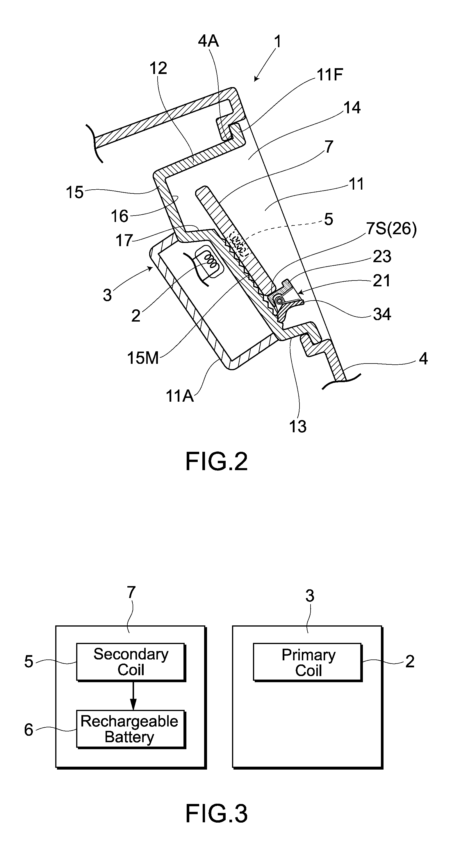
[0029]FIG. 1 to FIG. 8 show a first embodiment of the present invention. As shown in the drawings, the in-vehicle battery charging system 1 includes a battery charger 3 with a built-in primary coil 2 acting as an energy transmitting unit. The battery charger 3 is housed in an instrumental panel 4 of a vehicle 8 to be used to contactlessly charge an object 7 to be charged including a secondary coil 5 acting as an energy receiving unit and a rechargeable battery 6. Here, the object 7 to be charged is a mobile terminal with a wireless function, and examples of such mobile terminal may include mobile electronic devices which enable information communication, as represented by a cellular phone, a smart phone, and an UMPC (Ultra Mobile Personal Computer).
[0030]As shown in FIGS. 1 and 2, the battery charger 3 of the in-vehicle battery charging system 1 is mounted in the following manner, with the structure described hereinbelow: a housing portion 11 in which the object 7 to be charged can ...
second embodiment
[0048]FIG. 9 shows a second embodiment. The same symbols are attached to parts the same as those in the first embodiment and the detailed description thereof is omitted, while a feature specific to the second embodiment is described in detail hereinbelow. The object 7 to be charged in the present embodiment is a mobile terminal with a wireless function and an information display function, having a built-in GPS device 41. The object 7 to be charged displays, on a display section 7H thereof, positional information containing positioning results obtained by the GPS device 41, and travelling conditions such as a vehicle speed and the like together with map information. In this case, the object 7 to be charged is placed on the mounting surface 15M with the display section 7H thereof surfaced on a driver or passenger side.
[0049]Further, the battery charger 3 of the in-vehicle battery charging system 1 is provided with a control unit 51 and a communication unit 52. This communication unit ...
third embodiment
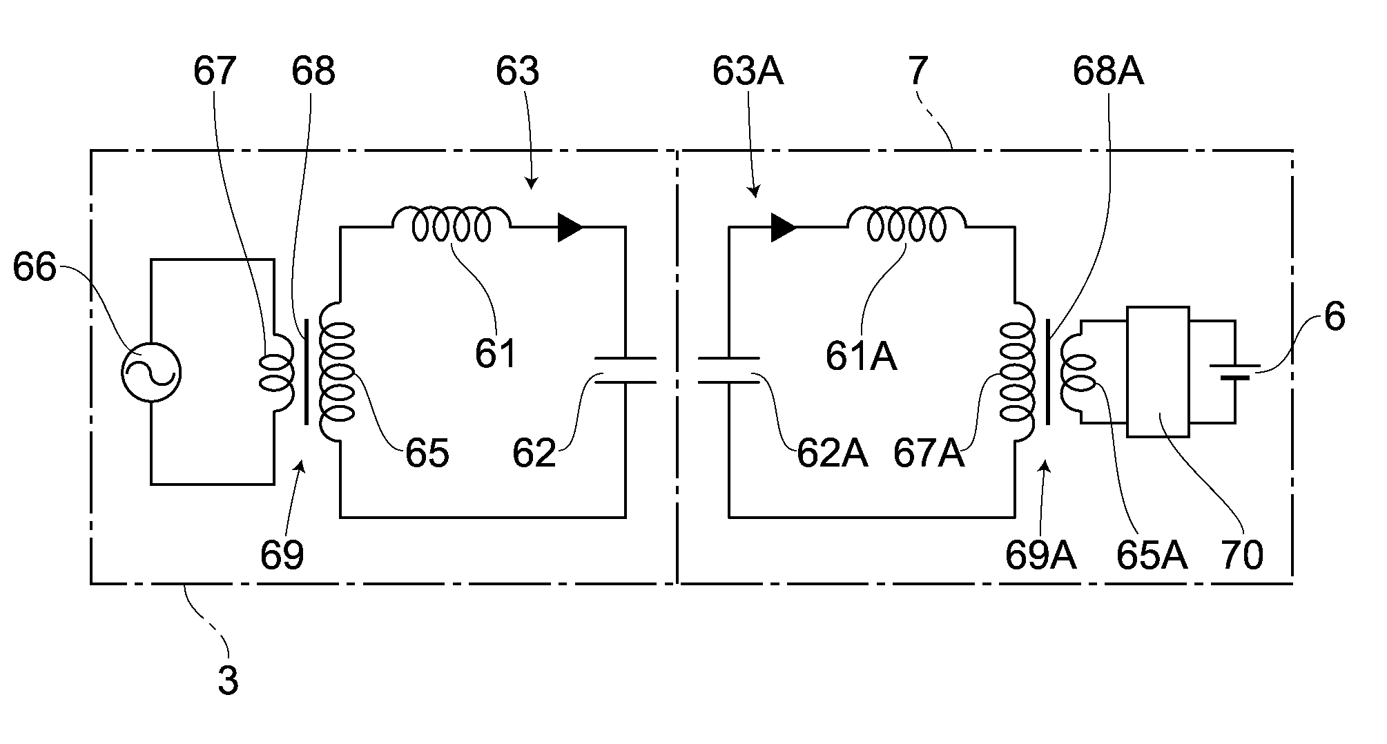
[0054]FIG. 10 shows a third embodiment of the present invention. The same symbols are attached to parts the same as those in each of the above embodiments and the detailed description thereof is omitted, while a feature specific to the third embodiment is described in detail hereinbelow. In the third embodiment, there is provided an in-vehicle battery charging system 1 for charging a battery through an electric field coupling system. As shown in FIG. 10, the battery charger 3 comprises an electric power transmitting resonant circuit 63 including an inductive element 61 and a capacitive element 62 acting as an energy transmitting unit, while the object 7 to be charged comprises an electric power receiving resonant circuit 63A including an inductive element 61A and a capacitive element 62A acting as an energy receiving unit. Here, the capacitive element 62 is arranged at a position of the primary coil 2.
[0055]Further, the electric power transmitting resonant circuit 63 is provided wit...
PUM
 Abstract
Description
Claims
Application Information
 - Generate Ideas
- Intellectual Property
- Life Sciences
- Materials
- Tech Scout
- Unparalleled Data Quality
- Higher Quality Content
- 60% Fewer Hallucinations
Browse by: Latest US Patents, China's latest patents, Technical Efficacy Thesaurus, Application Domain, Technology Topic, Popular Technical Reports.
© 2025 PatSnap. All rights reserved.Legal|Privacy policy|Modern Slavery Act Transparency Statement|Sitemap|About US| Contact US: help@patsnap.com