Image capturing apparatus and focus detection method

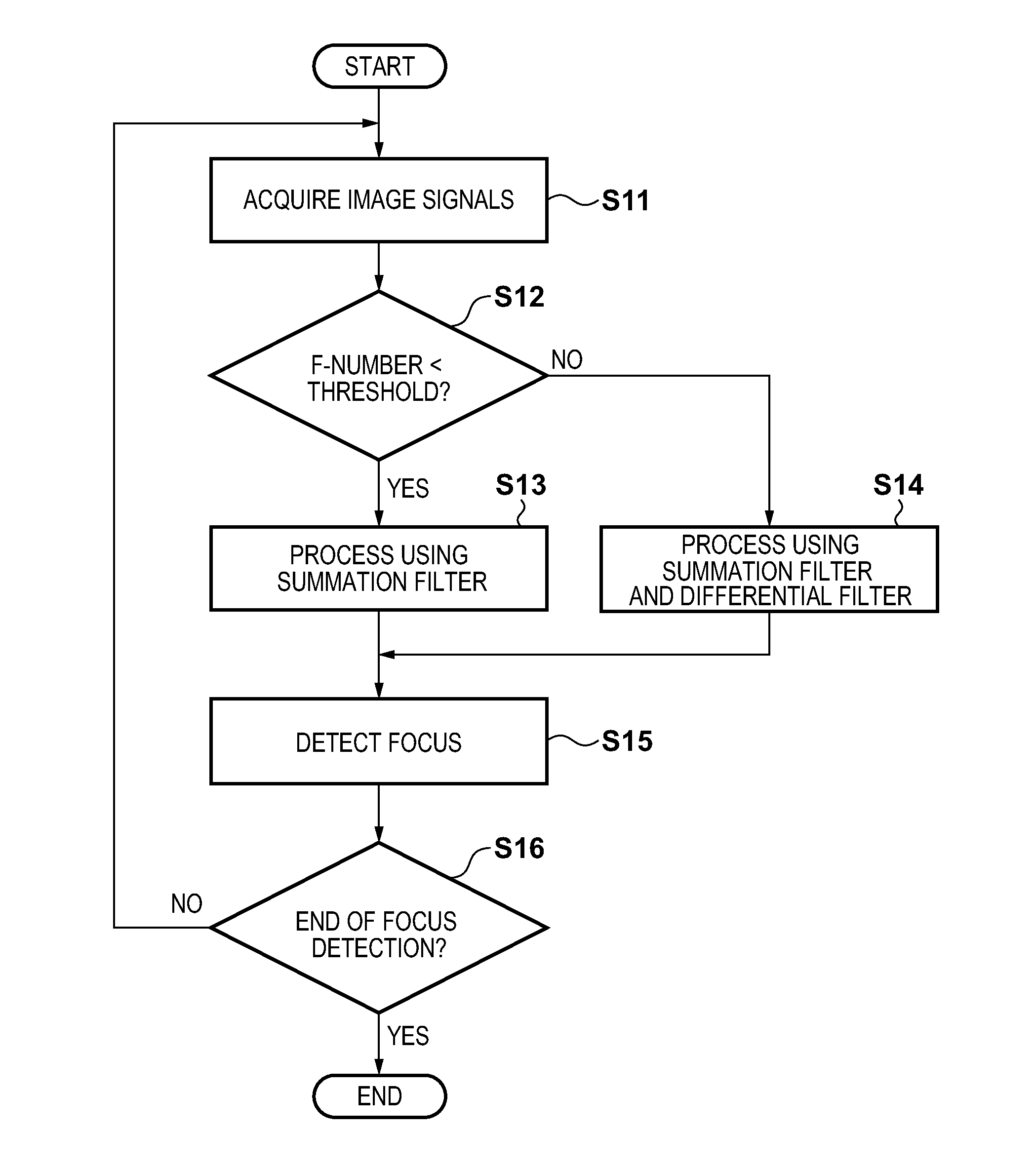
a technology of image capturing and focus detection, which is applied in the field of focus detection technique, can solve the problems of difficulty in even detecting the direction of defocus, large asymmetry of image signals, and insufficient pupil division characteristic near the optical axis

Active Publication Date: 2013-06-13
CANON KK
View PDF18 Cites 17 Cited by
  • Summary
  • Abstract
  • Description
  • Claims
  • Application Information

AI Technical Summary

Benefits of technology

[0013]According to a sixth aspect of the present invention, there is provided a focus detection method of performing focus detection based on a pair of image signals obtained from an image sensor including a plurality of two-dimensionally arranged pixels including pixels each having a pair of photoelectric conversion units capable of outputting the pair of image signals obtained by independently receiving a pair of light beams that have passed through different exit pupil regions of an imaging optical system, the method comprising: an acquisition step of acquiring an f-number and a pupil distance of the imaging optical system; an evaluation step of evaluating an effect of vignetting based on the f-number and the pupil distance; a filtering step of performing filtering of the pair of image signals using a first filter formed from a summation filter when the effect of vignetting is more than a predetermined threshold, and performing filtering of the pair of image signals using a second filter formed from the summation filter and a differential filter when the effect of vignetting is not more than the threshold; and a focus detection step of performing focus detection by a phase difference method based on the pair of image signals that have undergone the filtering in the filtering step.

Problems solved by technology

In an apparatus that divides the pupil by dividing a photoelectric conversion unit, however, the pupil division characteristic near the optical axis is sometimes insufficient.
In addition, when the f-number is small, the asymmetry of an image signal is large.
For this reason, distortion is enhanced by differential filtering, which may cause a difficulty in even detecting the direction of defocus.

Method used


Image

  • Image capturing apparatus and focus detection method
  • Image capturing apparatus and focus detection method
  • Image capturing apparatus and focus detection method

Examples


Embodiment Construction

[0026]Embodiments of the present invention will be described in detail in accordance with the accompanying drawings. Each of the embodiments of the present invention described below can be implemented solely or as a combination of a plurality of the embodiments or features thereof where necessary or where the combination of elements or features from individual embodiments in a single embodiment is beneficial.

[0027](Configuration of an Image Capturing Apparatus)

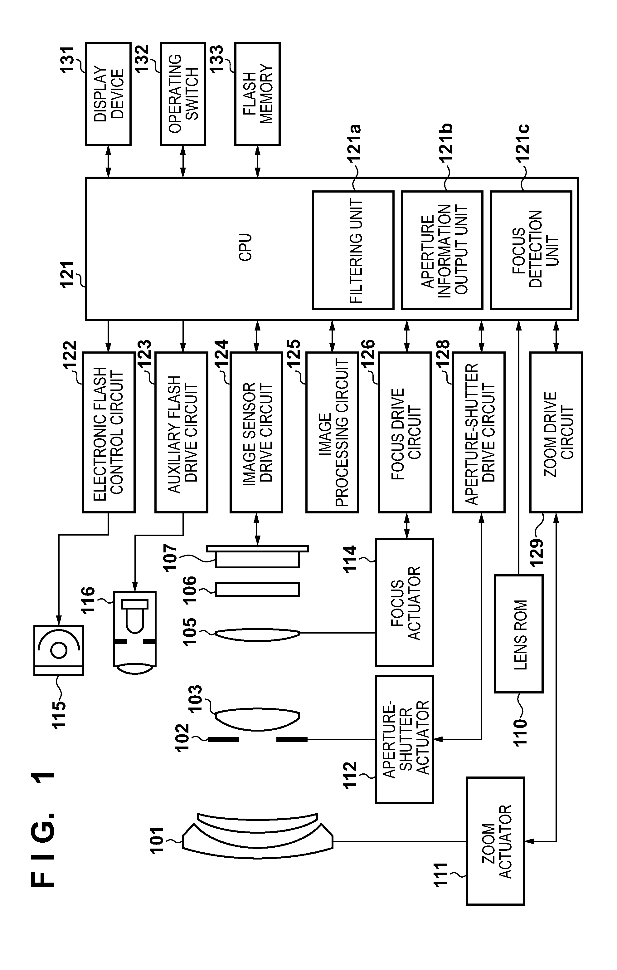
[0028]FIG. 1 is a configurational diagram of an image capturing apparatus according to an embodiment of the present invention, showing an electronic camera in which a camera body including an image sensor and a photographing optical system are integrated into a single unit. In FIG. 1, a first lens group 101 is disposed on the front end of a photographing optical system (imaging optical system), and supported so as to be movable forward and backward along an optical axis. An aperture-shutter 102 adjusts the diameter of its open...


PUM


Abstract

An image capturing apparatus performs focus detection based on a pair of image signals obtained from an image sensor including pixels each having a pair of photoelectric conversion units capable of outputting the pair of image signals obtained by independently receiving a pair of light beams that have passed through different exit pupil regions of an imaging optical system. In the focus detection, an f-number of the imaging optical system is acquired, the pair of image signals undergo filtering using a first filter formed from an summation filter when the f-number is less than a predetermined threshold, or using a second filter formed from the summation filter and a differential filter when the f-number is not less than the threshold, and focus detection is performed by a phase difference method based on the pair of filtered image signals.

Description

BACKGROUND OF THE INVENTION[0001]1. Field of the Invention[0002]The present invention relates to a focus detection technique used in an image capturing apparatus such as an electronic camera.[0003]2. Description of the Related Art[0004]A conventional focus detection apparatus adopting a pupil division method using an image sensor is disclosed in, for example, Japanese Patent Laid-Open No. 01-216306. Such a focus detection apparatus adopting a pupil division method can detect a defocus amount by performing measurement only once even in a greatly defocused state. This method is promising because high-speed focus adjustment is possible.[0005]On the other hand, applying differential filtering to an image signal is generally performed as a technique to improve the accuracy of defocus amount detection. An example of the effect of the differential filtering is an improvement in the direction detection accuracy. Japanese Patent Laid-Open No. 07-318793 discloses performing two types of diffe...

Claims


Application Information

Patent Timeline
Patent Type & Authority Applications(United States)
IPC IPC(8): H04N5/232
CPCH04N5/23212H01L27/14645H04N23/672H04N25/704H04N25/134
Inventor YOSHIMURA, YUKIFUKUDA, KOICHI
Owner CANON KK
Why Eureka
Try Eureka