Transmitting electrical power and communication signals

a technology of electrical power and communication signals, applied in the direction of digital transmission, baseband system details, drill/well adaptable systems, etc., can solve the problems of subsea components consuming electrical power, electrical noise and transients being generated, and techniques

Active Publication Date: 2013-06-13
GE OIL & GAS UK LTD
View PDF3 Cites 12 Cited by
  • Summary
  • Abstract
  • Description
  • Claims
  • Application Information

AI Technical Summary

Benefits of technology

[0006]According to an embodiment of the present invention, a system for transmitting electrical power and communication signals is provided. The system comprises a transmission line, a source of electrical power for supplying electrical power to the transmission line, a first communication unit configured to supply communication signals to the transmission line, a power extraction unit configured to extract and use electrical power from the transmission line, a second communication unit configured to receive communication signals from the transmission line; and a control unit configured to control operation of the system. The source supplies electrical power to the transmission line for respective periods of time which are different from respective periods of time in which the first communication unit supplies communication signals to the transmission line.

Problems solved by technology

However, this technique does have some inherent disadvantages as follows.
At the subsea equipment level there is a need to utilize bulky equipment, such as communications blocking filters and diplexers, to separate and retrieve the communication signals from the power signal and this process can result in electrical noise and transients being generated.
These subsea components also consume electrical power
The quality of the electrical power generated topside and transmitted through the umbilical cable may be poor and contain electrical noise and harmonics of the typically 50 / 60 Hz electrical power frequency and these may interfere with the lower power communication signals which are superimposed on the electrical power signal.
Sudden voltage transients (such as those caused by switching surges or sudden changes to the electrical load) can interfere with the high frequency communication signals.

Method used


Image

  • Transmitting electrical power and communication signals
  • Transmitting electrical power and communication signals
  • Transmitting electrical power and communication signals

Examples


Embodiment Construction

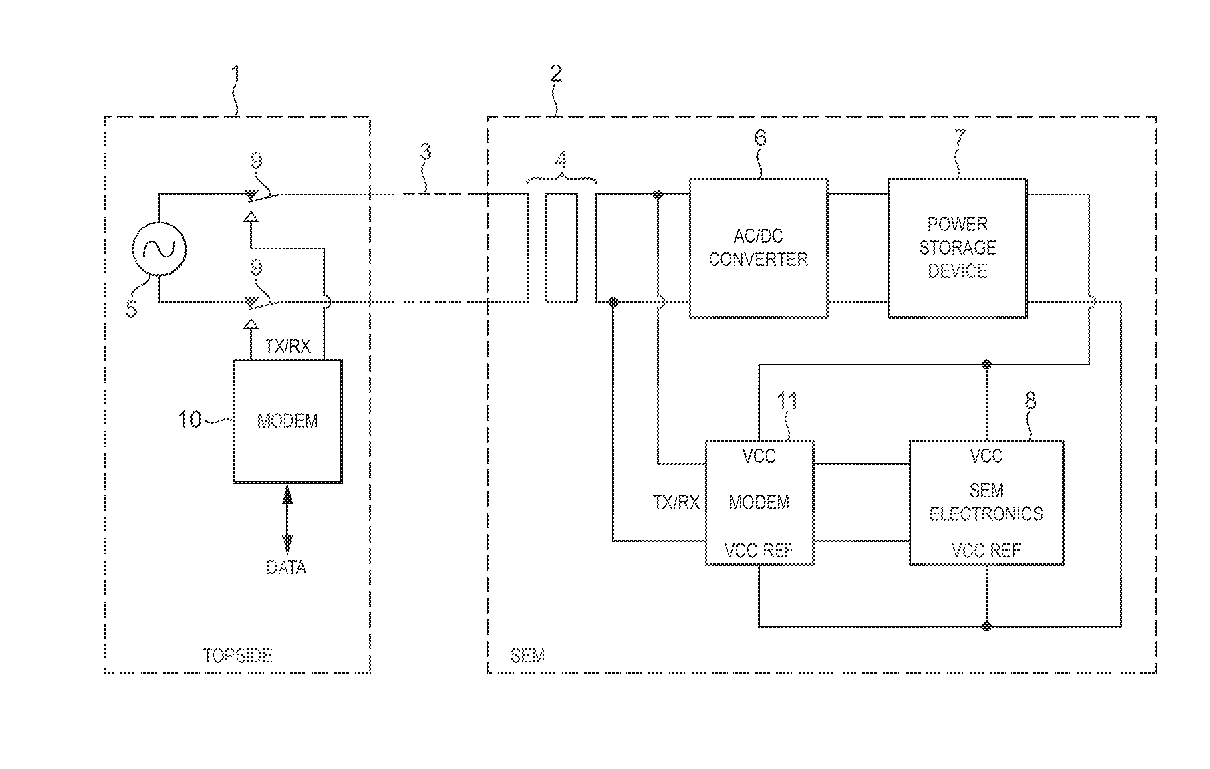
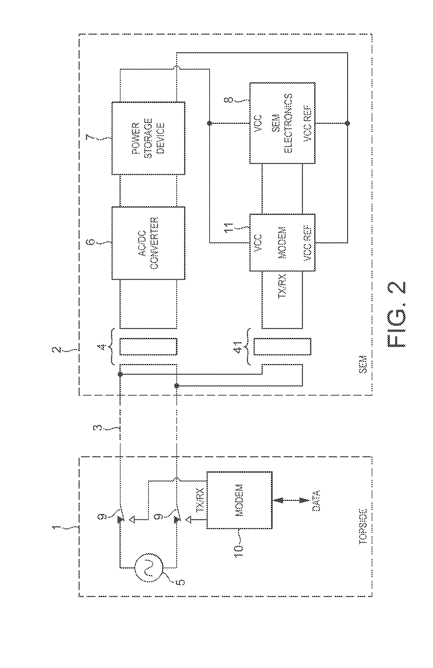
[0012]Two different offshore applications which use similar equipment configurations are described to illustrate how a time division multiplexing technique (usually used for transmitting different types of communications data in separate sequenced time slots) can be used as an alternative to the current COP technique to transmit both electrical power and communication signals along the same transmission line. However, embodiments of the invention are applicable to other situations where electrical power and communication signals are to be transmitted along the same transmission line.

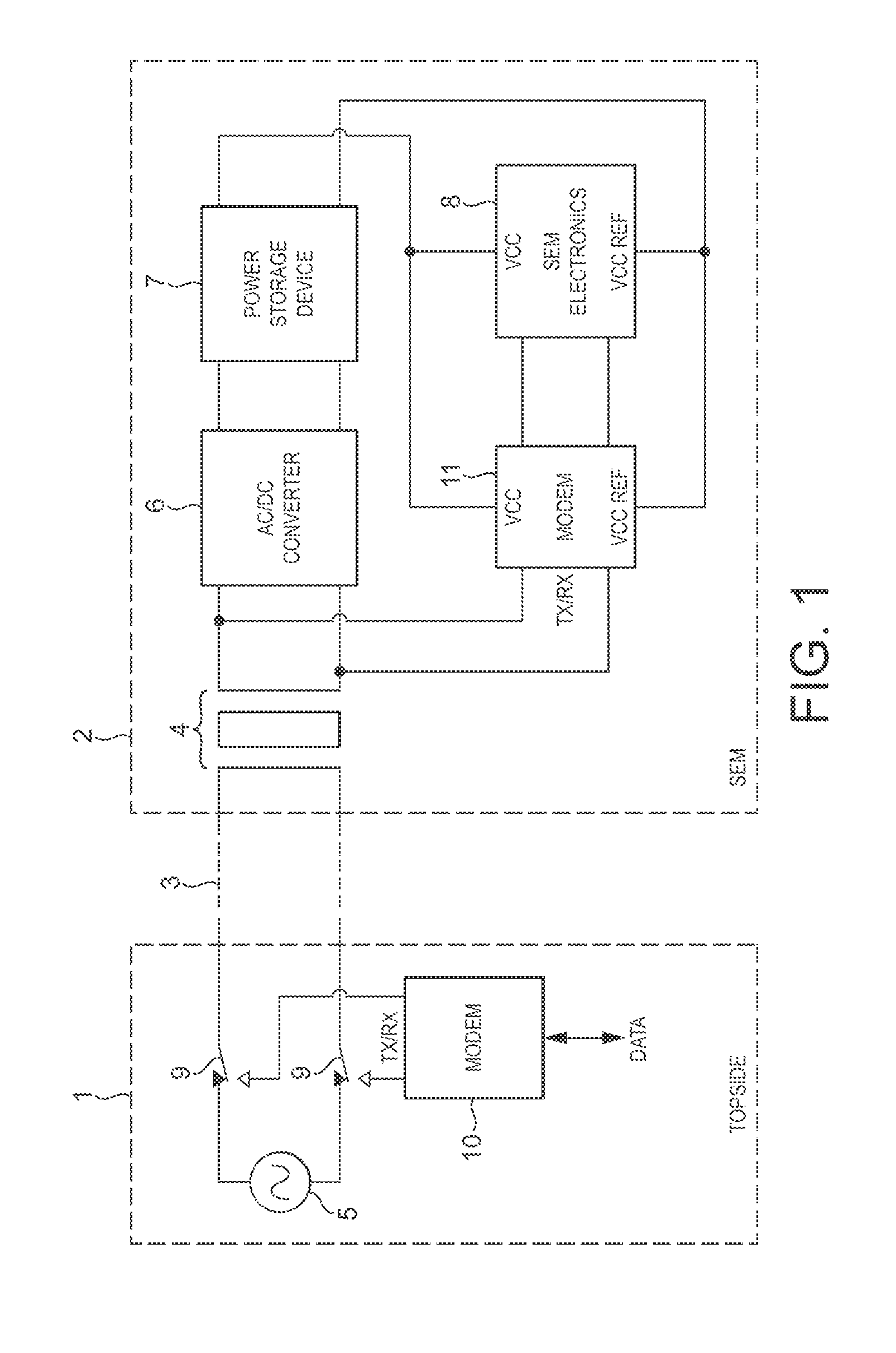
[0013]FIG. 1 illustrates the use of an embodiment of the invention in a production control system of a subsea hydrocarbon well when applied to the transmission of communication signals (control and instrumentation) between topside and subsea equipment along a transmission line in an umbilical cable. The figure shows the interface between a topside surface platform 1 and a subsea end, specifically at a su...


PUM


Abstract

A system for transmitting electrical power and communication signals is provided. The system comprises a transmission line, a source of electrical power for supplying electrical power to the transmission line, a first communication unit configured to supply communication signals to the transmission line, a power extraction unit configured to extract and use electrical power from the transmission line, a second communication unit configured to receive communication signals from the transmission line; and a control unit configured to control operation of the system. The source supplies electrical power to the transmission line for respective periods of time which are different from respective periods of time in which the first communication unit supplies communication signals to the transmission line.

Description

BACKGROUND OF THE INVENTION[0001]Embodiments of the present invention relate to transmitting electrical power and communication signals. One of the enabling techniques used in offshore production control systems for hydrocarbon extraction wells, to transmit control and instrumentation signals between topside equipment and subsurface equipment installed on the seabed, is the use of communications-on-power (COP) where communication signals are superimposed on an electrical power signal and transmitted simultaneously with the power signal along a power transmission line in an umbilical cable.[0002]This method is employed to reduce the number of electrical lines needed within the umbilical cable, which provides the main interface between topside and subsurface equipment for hydraulic and electrical power. Using COP eliminates the need for separate power and communication lines within the umbilical cable, thereby reducing its overall cost. However, this technique does have some inherent ...

Claims


Application Information

Patent Timeline
Patent Type & Authority Applications(United States)
IPC IPC(8): H04L25/02
CPCH04L25/026H04B2203/5475H04B2203/5412H04B3/546
Inventor PUCHIANO, SILVIUMORLEY, GRAHAMSMART, HILTONDAVIS, JULIANSIMPSON, STEVEN LEWIS CHARLES
Owner GE OIL & GAS UK LTD
Why Eureka
Try Eureka