Microspeaker with inner resonance chamber

a technology of inner resonance and microspeaker, which is applied in the direction of transducer details, transducer diaphragms, electrical transducers, etc., can solve the problems of low frequency sound quality degradation, difficult to reproduce natural sounds, and difficult to achieve the effect of sound reproduction

Active Publication Date: 2013-06-13
BUJEON
View PDF5 Cites 35 Cited by
  • Summary
  • Abstract
  • Description
  • Claims
  • Application Information

AI Technical Summary

Benefits of technology

[0011]Therefore, the present invention has been made in view of the above problems, and it is an object of the present invention to provide a microspeaker whic

Problems solved by technology

That is, since the forward sound radiated forward from the front side of the vibration plate has a phase difference of 180° from the rearward sound radiated rearward from the rear side of the vibration plate, interference may occur when the forward sound meets the rearward sound in a narrow space, resulting in degradation of quality of low frequency sounds.
Therefore, if the rearward sound generated at the rear side of the vibration plate is not blocked, low frequency sounds undergo destructive interference, and only high frequency sounds remain, thereby making it difficult to reproduce natural sounds.
Here, if the rearward sound generated at the rear side of the vibration plate is completely blocked, air pressure at the rear side of the vibration plate rises to cause a narrow amplitude and shift of the sound to a higher frequency range, leading to degradation of sound quality.
However, as the size of the enclosure increases due to the back volume, there is a problem of causing the microspeaker module to be thicker.
Meanwhile, for a microspeaker used for an in-ear earphone, interference between the forward sound and the rearward sound rarely occur

Method used


Image

  • Microspeaker with inner resonance chamber
  • Microspeaker with inner resonance chamber
  • Microspeaker with inner resonance chamber

Examples


Embodiment Construction

[0043]Reference will now be made in detail to the embodiments of a microspeaker with an inner resonance chamber according to the present invention, examples of which are illustrated in the accompanying drawings.

[0044]It should be understood that the terms used in the specification and appended claims should not be construed as limited to general and dictionary meanings but should be construed based on the meanings and concepts according to the spirit of the present invention on the basis of the principle that the inventor is permitted to define appropriate terms for best explanation. The embodiments described in the specification and shown in the drawings are purely illustrative and are not intended to represent all aspects of the invention, such that various equivalents and modifications may be made without departing from the spirit of the invention.

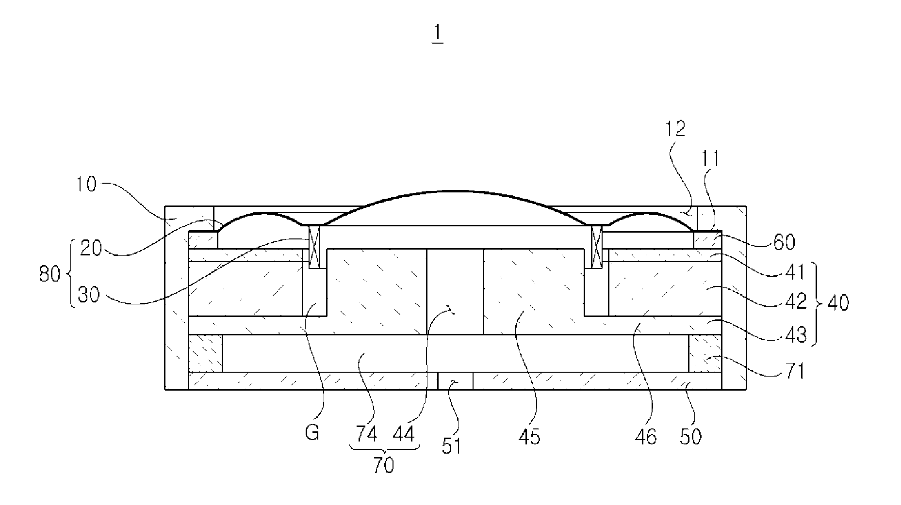
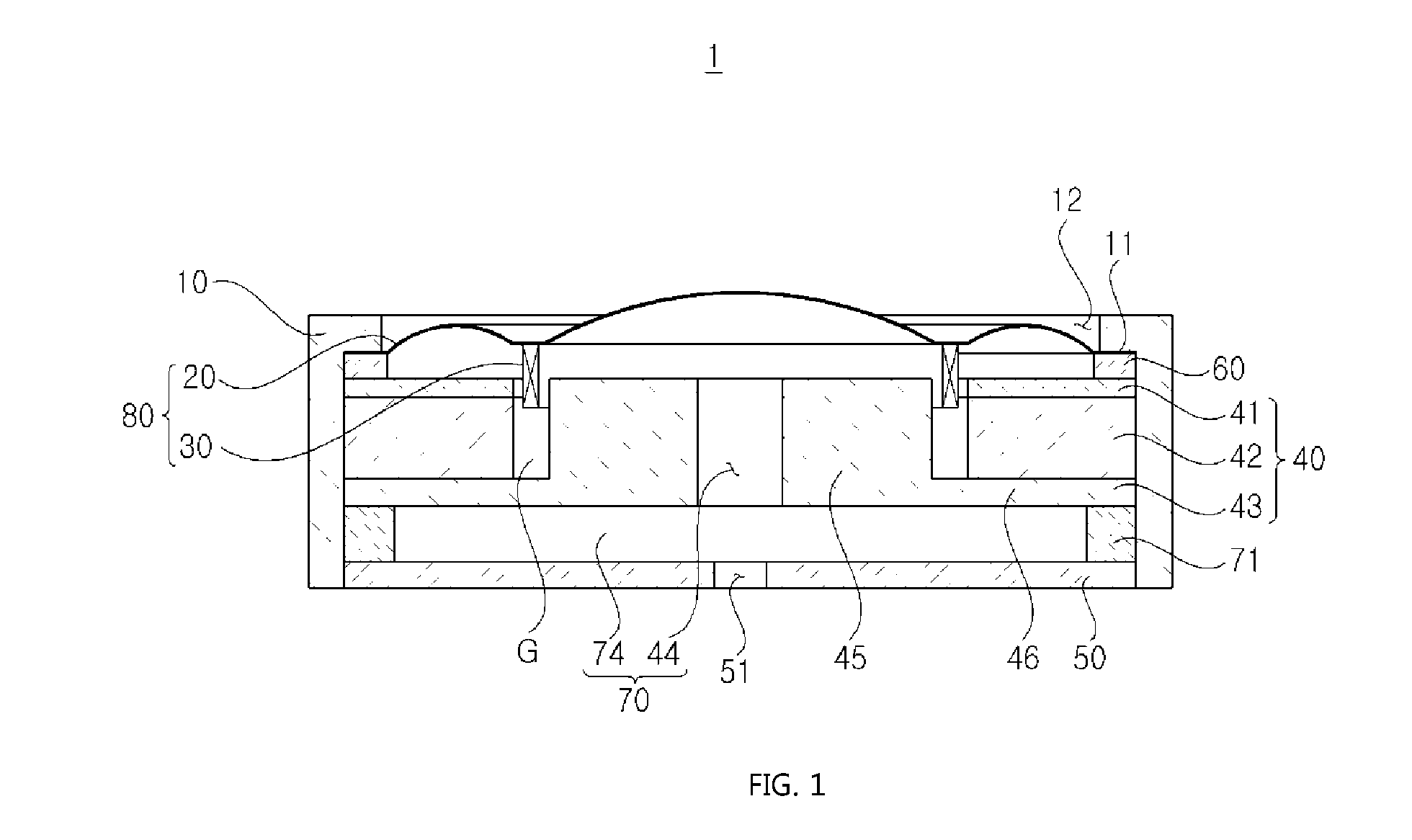
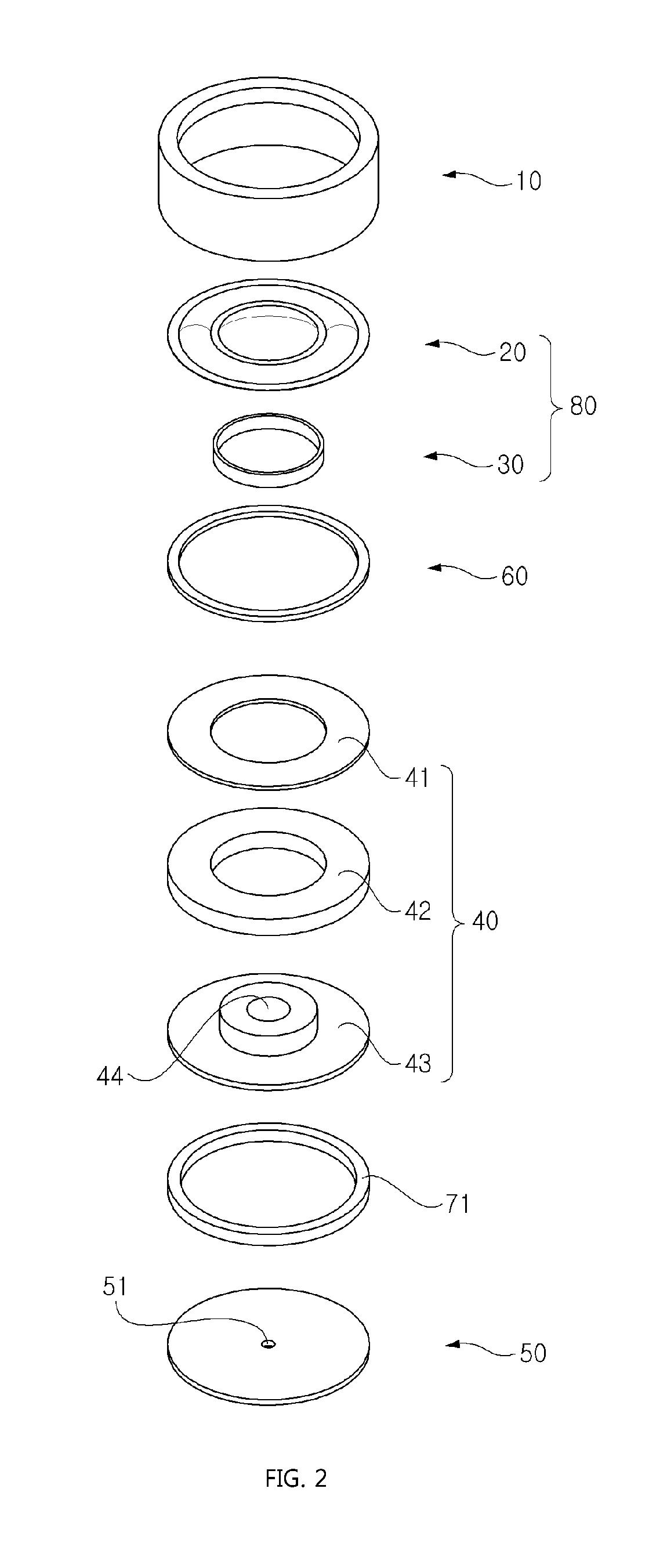
[0045]As shown in FIGS. 1 and 2, a microspeaker 1 with an inner resonance chamber (hereinafter, referred to as a microspeaker) accordi...


PUM


Abstract

Disclosed is a microspeaker with an inner resonance chamber, more particularly a microspeaker with an inner resonance chamber which improves quality of sound and enables slim and compact design of the microspeaker by blocking rearward sound generated at the rear side of the vibration plate to prevent interference of a rearward sound with a forward sound generated at the front side of a vibration plate and installing a chamber with a specific volume within the microspeaker to allow the rearward sound to cause resonance.

Description

BACKGROUND OF THE INVENTION[0001]1. Field of the Invention[0002]The present invention relates to a microspeaker with an inner resonance chamber, and more particularly to a microspeaker with an inner resonance chamber which improves quality of sound and enables slim and compact design of the microspeaker by blocking rearward sound generated at the read side of the vibration plate to prevent interference of a rearward sound with a forward sound generated at the front side of a vibration plate and installing a chamber with a specific volume within the microspeaker to allow the rearward sound to cause resonance.[0003]2. Description of the Related Art[0004]In general, portable electronic devices including portable communication terminals, laptop computers, and MP3 players are provided with a microspeaker for converting an electric signal into an acoustic signal. Such a microspeaker converts electrical energy into mechanical energy by positioning a voice coil in an air gap of the magnetic...

Claims


Application Information

Patent Timeline
IPC IPC(8): H04R9/02
CPCH04R1/2811H04R7/127H04R2499/11H04R9/027H04R9/06
Inventor SEO, DONG HYUN
Owner BUJEON
Why Eureka
Try Eureka