
Systems and devices for removing materials from vacuum truck tanks

a vacuum truck and tank technology, applied in the field of vacuum truck tank system and device, can solve the problems of inefficient use of energy and time, increased fuel and man-hours, and disadvantages of conventional vacuum truck and system

Inactive Publication Date: 2013-06-13
PRO TECH ENTERPRISES +1
View PDF8 Cites 10 Cited by
  • Summary
  • Abstract
  • Description
  • Claims
  • Application Information

AI Technical Summary

Benefits of technology

The patent text describes a system and method for efficiently removing materials from vacuum truck tanks. The conventional methods of emptying the tank through hoists or other mechanisms are inefficient and require additional power and time. The system and method described herein offer a more efficient and safe way to remove materials from the tank. The system includes a tank with a removable bottom that can be easily emptied, and the collected materials can be easily transported to another location for disposal or processing. The system also includes various internal components such as a spray bar and a vacuum truck. Overall, the system and method described herein offer a more efficient and safe way to remove materials from vacuum truck tanks.

Problems solved by technology

However, there are a number of disadvantages associated with conventional vacuum trucks and systems.
These systems result in an inefficient use of energy and time.
In particular, the additional power and time needed to lift the entire tank to remove the collected materials results in additional expenses in the form of fuel and man-hours.
Furthermore, the mechanisms necessary to lift the tank are complex and result in an increased manufacturing, purchase, and maintenance costs.
In addition, these conventional systems are often ineffective.
For example, the vibrations of the vacuum trucks during travel or operation may compact collected materials within the tank, thereby causing the materials to adhere together and to the inner surfaces of the tank.
As a result, merely lifting or tipping the tank may be insufficient to remove the materials from the tank.
This is an ineffective, inefficient, and unsafe system and method of removing materials from a vacuum tank.
Forcing the operators to enter the tanks and manually remove the materials puts the operators in a dangerous situation that could result in injury from accident or overexertion.
In addition, the moving parts necessary to lift or tip the tank create additional pinch points, not to mention instability, that can cause injury to those working on or nearby the vacuum truck.

Method used


Image

  • Systems and devices for removing materials from vacuum truck tanks
  • Systems and devices for removing materials from vacuum truck tanks
  • Systems and devices for removing materials from vacuum truck tanks

Examples


Embodiment Construction

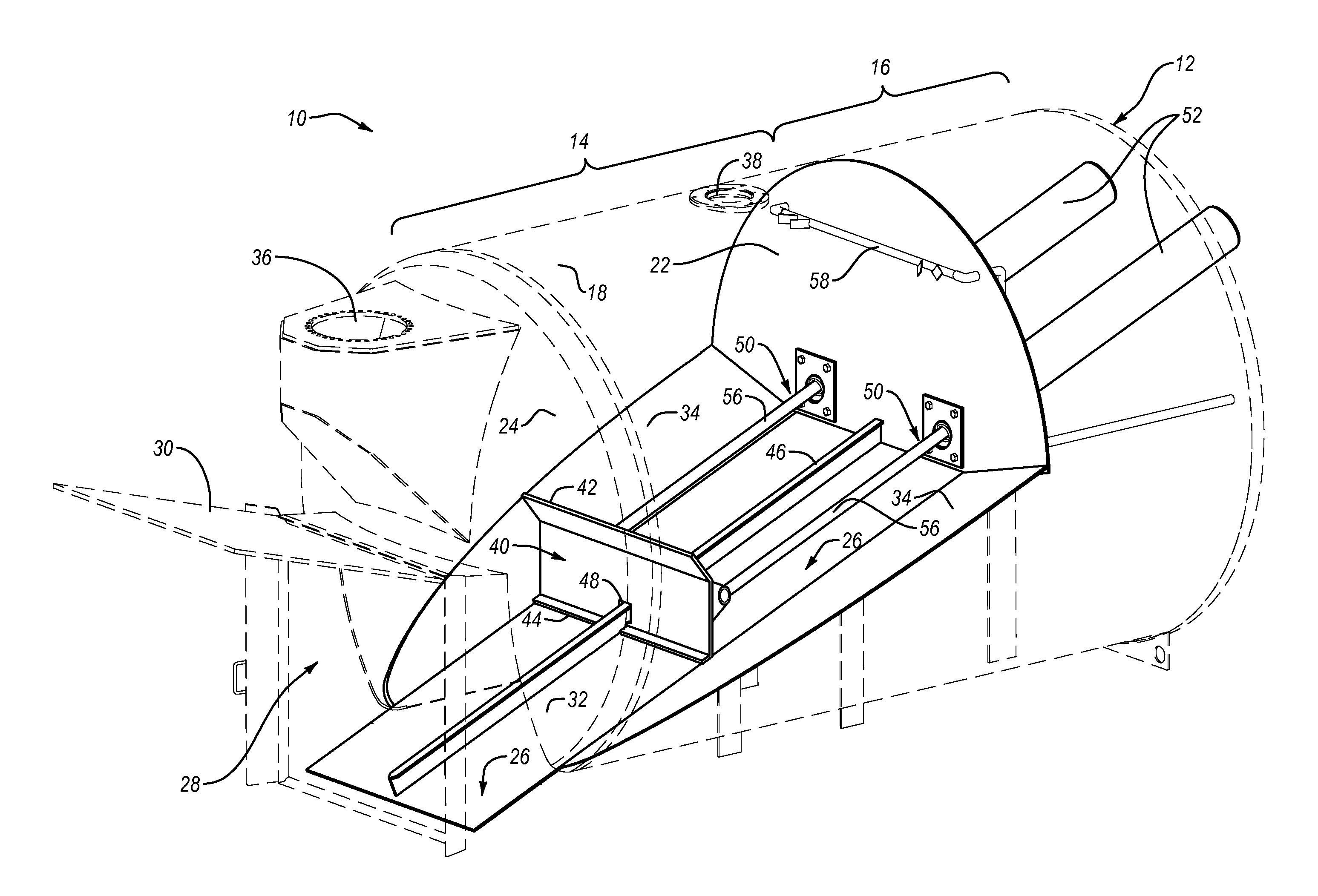
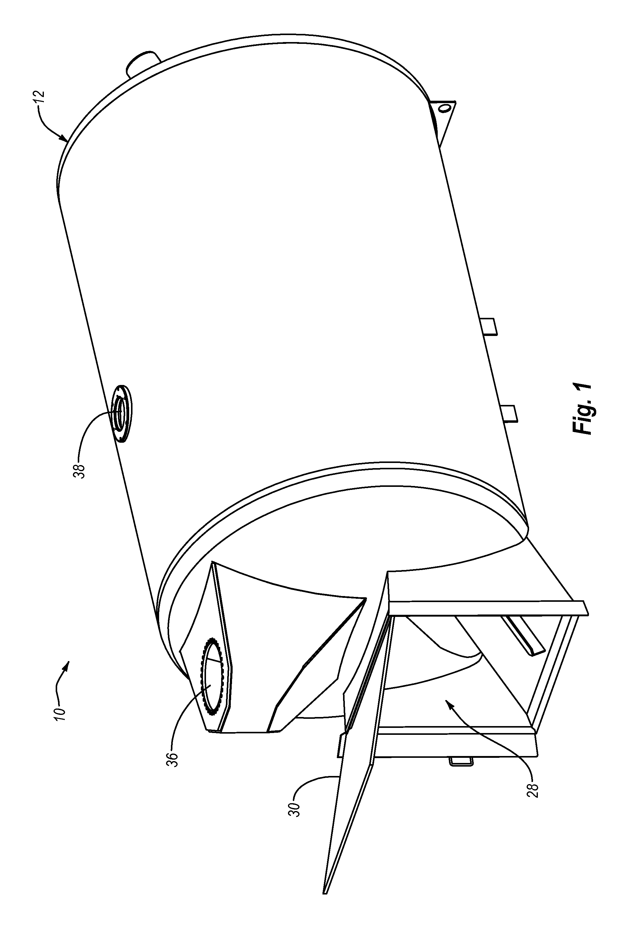
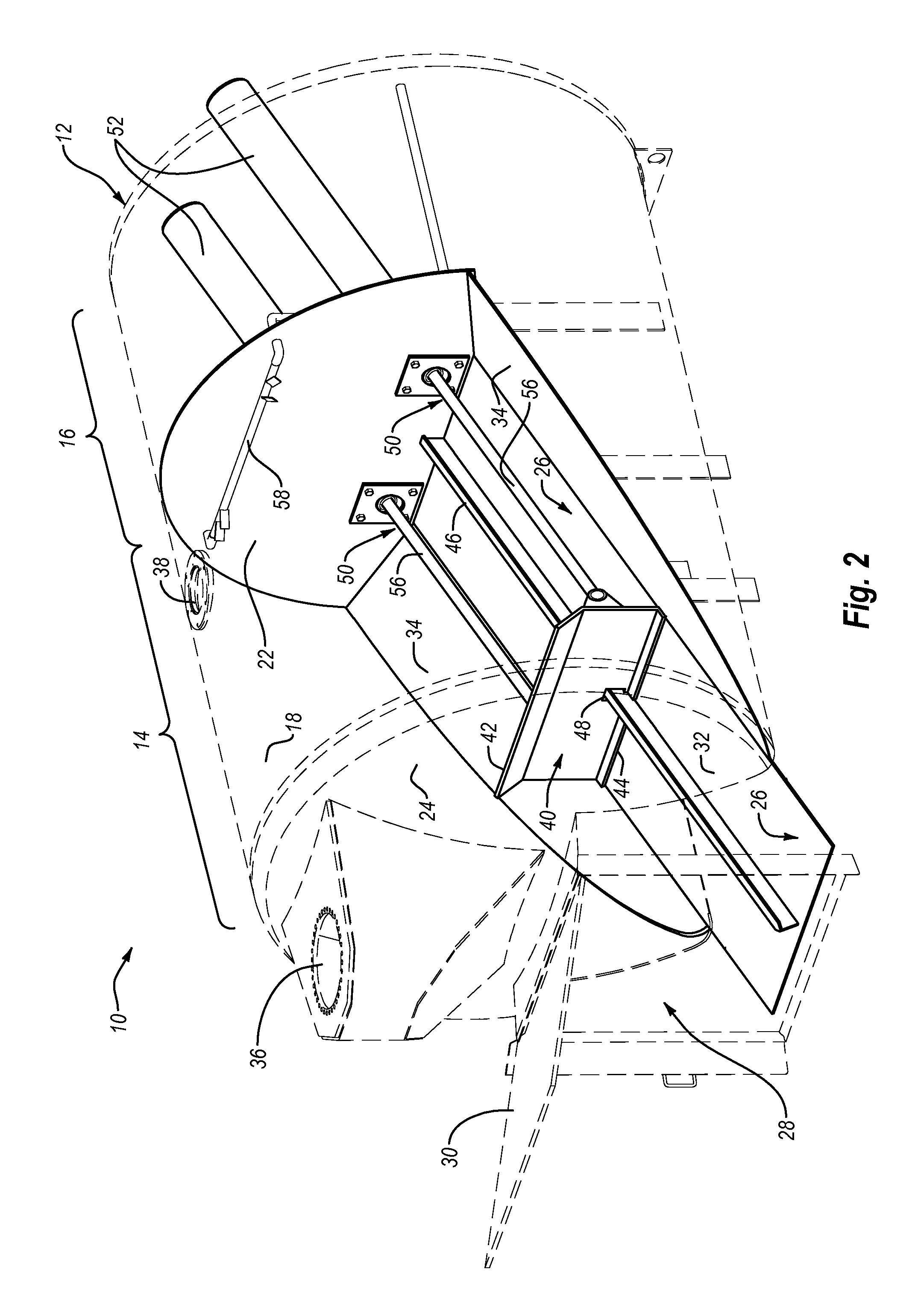
[0015]Exemplary systems and devices for removing materials from vacuum truck tanks are disclosed herein. As will be described in more detail below, in certain implementations, the systems and devices disclosed herein may be configured to allow a vacuum truck operator to efficiently, effectively, and safely remove collected materials from a tank of a vacuum truck. For example, the systems and devices disclosed herein may be configured to allow a vacuum truck operator to effectively remove collected materials from a vacuum truck's tank without the need for a mechanism to lift or tip the tank. In addition, the systems and devices disclosed herein may be configured to reduce or remove the need for manual intervention and physical labor to remove the materials from the vacuum truck's tank. Additional benefits and / or advantages will be apparent from the details disclosed herein.

[0016]As used herein, the term “vacuum truck” may be used to refer to any mobilized industrial vacuum loader inc...


PUM


Abstract

Systems and devices for removing materials from vacuum truck tanks are disclosed herein. An exemplary system for removing materials from a vacuum truck may include a tank having one or more walls enclosing the tank and an opening in the one or more walls to facilitate removal of materials from the tank; a blade positioned within the tank and configured to push materials towards the opening to remove or discharge collected materials from the tank; and a drive mechanism configured to selectively move the blade towards the opening in the tank. Additional systems and devices for removing materials from vacuum truck tanks are also disclosed herein.

Description

BACKGROUND OF THE INVENTION[0001]Vacuum trucks are truck-mounted heavy duty industrial vacuum loaders designed to pneumatically convey solids, liquids, sludge, slurry, or other materials through suction hoses into a collection tank. Vacuum trucks are utilized in a variety of industries (e.g., drilling, exploration, excavation, sewage collection, hazardous waste collection, refuse collection, etc.) for collecting a variety of materials. In addition to being useful in the collection of materials, vacuum trucks can also be used to transport the collected materials to another site for processing or disposal.[0002]As a specific example, in drilling operations, a fluid commonly referred to as “mud” is circulated from the surface, downward through a drill pipe and out openings in the drill bit at the bottom of a borehole. After exiting the drill bit at the bottom of the borehole, the mud along with other material from the borehole (often referred to collectively as “cuttings”), are pushed ...

Claims


Application Information

Patent Timeline
Patent Type & Authority Applications(United States)
IPC IPC(8): B60P3/16
CPCB60P1/60B60P1/006
Inventor HARMS, JR., GARY W.ROLLINS, WILLIAM DAVIDOROM, JENNIFER
Owner PRO TECH ENTERPRISES
Learn More